Table of Contents
Advertisement
Advertisement
Table of Contents

Related Manuals for Silca MARKER 2000


Summary of Contents for Silca MARKER 2000
- Page 1 Operating manual D430498XA vers . ®...
- Page 2 This manual has been drawn up by SILCA S.p.A. All rights reserved. No part of this publication may be reproduced or used in any form or any means (photocopying, microfilm or other) without the written permission of SILCA S.p.A. Published in: September 2002 Printed in Vittorio Veneto by SILCA S.p.A.
-
Page 3: Table Of Contents
INDEX GUIDE TO THE MANUAL ..................1 GENERAL......................2 MACHINE DESCRIPTION ..................3 Main Features....................4 Working parts ....................5 Technical data ..................... 6 Accessories provided .................. 6 TRANSPORT ......................7 Packing......................7 Transport ..................... 8 Unpacking....................8 Machine handling ..................8 MACHINE INSTALLATION and PREPARATION.......... - Page 4 Data from PC [F3]..................30 6.5.1 Connecting MARKER 2000 to a Personal Computer ......30 6.5.2 Transfer of data from Marker 2000 to Personal Computer ....30 SETTING THE ZEROES [F8] ................31 Regulating the sensors................31 TEST FUNCTIONS ....................33 MAINTENANCE ....................35 Trouble shooting..................
-
Page 5: Guide To The Manual
MARKER 2000 GUIDE TO THE MANUAL This manual has been produced to serve as a guide for users of the MARKER 2000 electronic marking machine. Read it carefully: it is essential if you wish to operate your machine safely and efficiently. -
Page 6: General
There are no further risks arising from the use of the MARKER 2000. ROTECTION AND SAFETY PRECAUTIONS FOR THE OPERATOR The MARKER 2000 is built entirely to standards. The operations for which it has been designed are easily carried out at no risk to the operator. -
Page 7: Machine Description
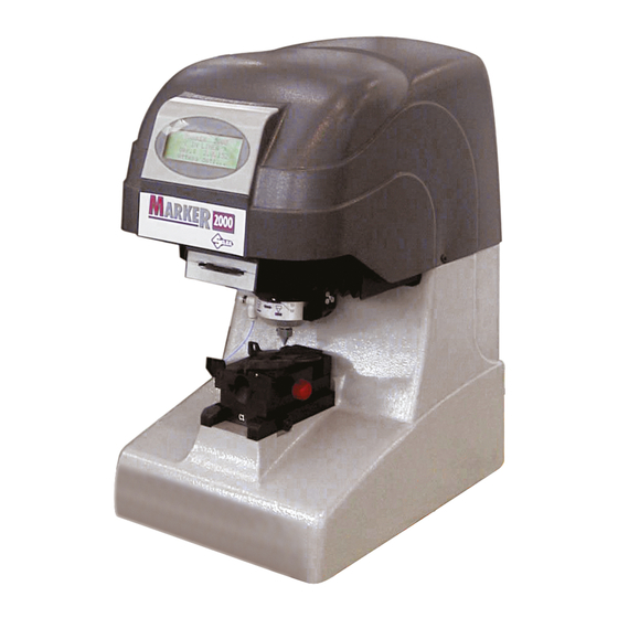
Operating manual - English MARKER 2000 MACHINE DESCRIPTION MARKER 2000 is an electronic device designed for marking keys, cylinders and medals using micro-dot technology. Accurately studied, it adds a high degree of marking precision and elegance to operating speed and ease of use. -
Page 8: Main Features
MARKER 2000 Operating manual - English Main Features • Movement Movement of the two axes (x-y) operates on ball couplings which ensure maximum smoothness and fluid movements, without play. • “C1” Clamp Designed to take any type of flat key, it features regulation of the key grip point so that its position is not altered. -
Page 9: Working Parts
Operating manual - English MARKER 2000 Working parts Fig. 6 A - marking punch B - display C - marking depth regulation ring D - tracking device D1 - tracking disk E - clamp slide F - slide-locking knob G - key-locking jaw... -
Page 10: Technical Data
Noise in use: Lp (A) = 85.3 dB (A) Accessories provided MARKER 2000 comes with a set of accessories for its operation and maintenance (tools, hex. wrenches, fuses, etc.) housed in the special tool holder and comprising: code D412279BA SET OF HEX WRENCHES GAUGING TEMPLATE 7 pcs. -
Page 11: Transport
The packed machine can be carried by one person. Packing The packing for MARKER 2000 is designed to ensure safe transportation and protect the machine and all its parts. The packing comprises two panels, (a) lower and (b) upper and two shells (c) in expanded material which enclose the machine (fig. -
Page 12: Transport
4) check the contents of the box, which should comprise: 1 MARKER 2000 marking machine packed in its protective shell. 1 set of documents, including: operating manual, spare parts list and guarantee. 1 power cable. -
Page 13: Machine Installation And Preparation
Checking for damage The MARKER 2000 is solid and compact and will not normally damage if transport, unpacking and installation have been carried out according to the instructions in this manual. -
Page 14: Regulation And Use Of The Machine
MARKER 2000 Operating manual - English REGULATION AND USE OF THE MACHINE Clamp The “C1” clamp, designed for the greatest possible number of flat keys, incorporates a rapid, easy to use system for securing and regulating the keys and comprises the following parts:... -
Page 15: Securing The Keys
Operating manual - English MARKER 2000 Securing the keys Take the clamp to the “tracking” position to facilitate positioning of the key. Ensure that the glass slide diffusor (P) is not in the way by rotating it outwards with knob (P1) (fig. 13). -
Page 16: Tracking
MARKER 2000 Operating manual - English Tracking Tracking defines the area in which the text will be contained. It comprises the following main parts: • Laser • Tracking disk (D1) with marking zone selection • Glass slide diffusor (P) By the combination of laser beam, disk and glass slide diffusor the marking zone is projected onto the head of the key. -
Page 17: Marking Punch Regulation Ring
The marking method is that of punching onto a surface a series of dots which form letters, numbers and symbols. Various fonts are available, such as: 6x8 12x14 (inclined) 8x14 8x16 For detailed information regarding the selection and use of the different fonts, see the software manual ”MARKER 2000 PROGRAM”. normal Bold font Fig. 19 Copyright Silca 2002... -
Page 18: Installation And Preliminary Operations [Set-Up]
MARKER 2000 Operating manual - English INSTALLATION AND PRELIMINARY OPERATIONS [SET-UP] The first operations to carry out are those of setting up: the language, type of keyboard connected and machine serial number. F2 = Marking When the machine is turned on, the... -
Page 19: Marking [F2]
Operating manual - English MARKER 2000 MARKING [F2] The marking program now includes a basic concept of a ‘model’, associated to which are: • configuration parameters • a text and/or special functions • a name to identify the model This chapter describes all the procedures for the creation of a model and marking. -
Page 20: Definition Of Model Parameters
(consult ch. 6.1.2-a to personalize the text format). The text to be marked can be formed by 4 S1 = SILCA SpA strings of 30 characters each and can contain S2 = Via PODGORA 20 small or capital letters. -
Page 21: 2-A Attributes Definition [F7]
6.1.2-a Attributes definition [F7] S1 = SILCA SpA ARKING WITH CUSTOMIZED FORMATTING S2 = Via PODGORA 20 Texts are customized for marking by setting different... -
Page 22: 2-B Entering Fixed Strings [F3]
MARKER 2000 Operating manual - English 6.1.2-b Entering fixed strings [F3] see ch. 6.4 "SPECIAL FUNCTIONS", page 26. 6.1.2-c Entering the automatic counters [F4] see ch. 6.4 "SPECIAL FUNCTIONS", page 26. 6.1.2-d Entering symbols [F2] see ch. 6.4 "SPECIAL FUNCTIONS", page 26. -
Page 23: Save Model
Operating manual - English MARKER 2000 6.1.4 Save model Zone = 1 : 1 Clamp = C1 The operator may now save or lose all Slide = 3 S = 1 O = 0 the information relating to the Model just created. -
Page 24: Marking [F10]
MARKER 2000 Operating manual - English 6.1.5 Marking [F10] Before marking, place the key in position on the Zone = 1 : 1 Clamp = C1 clamp (ch. 4.2, page 11) and take the clamp into the Slide = 3... -
Page 25: Glass Slide Customization [F2]
Pcs.= 1 of 1 Press key F2 to show the data for the glass slide setting. WARNING: the first 16 glass slides have been set up by Silca SILCA glass slide and cannot be altered. Glass slide N. Use the arrow keys... -
Page 26: Entering A New Tracking Zone [F5]
‘model’ can comprise four texts positioned independently of each other, with different formatting parameters (fig. 23). In this way a key can be marked in four tracking zones which are positioned separately from each other. SILCA SILCA S . p . A. (glass slide 2) (glass slide 2) Example:... -
Page 27: Fixed Strings [F4]
Operating manual - English MARKER 2000 Fixed strings [F4] Local marking A “string” is any text, such as: name, F2 = List of models surname, address, telephone number, etc. F3 = New model The operator can place in the memory... -
Page 28: List Of Models [F2]
MARKER 2000 Operating manual - English List of models [F2] Local marking The ‘List of Models’ contains all the F2 = List of models models created and memorized in the F3 = New model marker, up to a maximum of 50. -
Page 29: Delete Model [F5]
Operating manual - English MARKER 2000 6.3.3 Delete model [F5] Local marking This function makes it possible to delete a model 0 = [Temporary] from the list of models. 1 = AAAAAAA 2 = BBBBBB Position the cursor on the model to be eliminated and press key F5. -
Page 30: Special Functions
MARKER 2000 Operating manual - English SPECIAL FUNCTIONS 6.4.1 Entering fixed strings [F3] When generating a text (New Model) one or more strings from the “fixed string” list can be included (see ch. 6.1.2, page 16). Go to the “New model” function (ch. 6.1, page 15). -
Page 31: Entering Symbols [F2]
Operating manual - English MARKER 2000 • (02) Double Progressive Example with 3 pcs to be marked: This function is similar to the previous one (01). With it a progressive numerical series can be generated for marking, A001 1 with the addition of a counter connected to the number of A001 2 pieces. -
Page 32: Fixed Lines (Ctrl+F2)
As described in the chapter.6.1.2, page 16, each marking area is subdivided equally into as many different parts as there are lines to be marked, except where the last lines are blank. S1= SILCA S. p. A. SI LCA S . p. A... -
Page 33: Special Characters
Operating manual - English MARKER 2000 Special characters 6.4.5 The set of characters which can be used by the electronic marking machine includes all those in the ANSI table. If the character required is not on the keyboard connected to the marking machine, it can be entered through a combination of keys: Example with an English keyboard: to enter Ä... -
Page 34: Data From Pc [F3]
Data from The marker is predisposed to receive models to be marked created on a PC through the Marker 2000 Program. Consult ch. 6.5.1 for further details on how to connect the marker to the PC and see the Marker 2000 Program 0perating Manual for the method of transmitting the models created to the marker. -
Page 35: Setting The Zeroes [F8]
Operating manual - English MARKER 2000 SETTING THE ZEROES [F8] Repeat the operations listed in Ch. 5 "Installation Tast.= IT and preliminary operations [SET-UP]", up to the following display: Matr.= 123456789012345 Pcs. tot.= Place the template (D5) in position on the clamp so that the top end butts against the stop “F1”. - Page 36 MARKER 2000 Operating manual - English sensore Y sensore X sensore Y sensore X Fig. 28 WARNING: position the glass slide (P) over the key (fig. 28). Place the clamp in the "tracking” position. Place clamp Move the disk (marking area) until glass slide No.1 is in tracking position.
-
Page 37: Test Functions
If the TEST gives undesirable results, see 102 = Micro clamp chapter 9.1 "Trouble shooting" and, if necessary, contact the Silca Service Centre. [F1] help UP,DOWN,F10=S e l e c t Press key F1 to gain access to the guide. - Page 38 MARKER 2000 Operating manual - English Test 103 = Magnet 103 = Magnet Take the clamp to the “tracking” position. When ENTER key on the keyboard is pressed an Move point to free impulse is sent to the marking punch.
-
Page 39: Maintenance
9.8, page 42) Message on display: check the operation of the cooling fan. ALARM If the fan is working properly, leave the machine off and contact a Silca Service Centre Temperature is over max. foreseen Turn off Marker! Copyright Silca 2002... -
Page 40: Replacing The Tracking Unit
The above-mentioned indications of probable causes of the faults described are purely indicative and do not represent a complete list of all possible causes of faulty operation. If you are unable to trace the cause of a fault, contact the Silca Service Centre. Replacing the tracking unit 1) turn off the master switch and remove the plug. -
Page 41: Removing The Upper Cover
Operating manual - English MARKER 2000 Removing the upper cover To gain access to some parts of the machine for maintenance purposes (e.g. belt tension-replacement, display replacement) the top cover (Q) must be removed. Proceed as follows. 1) turn off the machine and remove the plug. -
Page 42: Replacing The Belts And Adjusting Tension
MARKER 2000 Operating manual - English Replacing the belts and adjusting tension If the top of the machine begins to vibrate, check the condition and tension of the belts, as follows: 1) turn off the master switch and remove the plug. - Page 43 Operating manual - English MARKER 2000 EPLACING THE AXIS BELT 1) turn off the master switch and remove the plug. 2) remove the upper cover (ch.9.4) and place next to the machine, without disconnecting the wiring to the display. 3) remove the clamp (C1) (fig. 35).
-
Page 44: Replacing The Display
Fuses must always be replaced with others of same type (rapid or delayed) and with the same amps, as given in the manual. There are five fuses in the MARKER 2000. • 2 fuses: 3.15 Amps rapid (220V) - Page 45 Operating manual - English MARKER 2000 • 3 fuses: F1, F2 and F3 F1 = 1 Amps delayed protects the +24Vdc for all input/output signals and laser tracking. F2 = 2 Amps delayed protects the +5Vdc required for operation of the microprocessor.
-
Page 46: Replacing The Control Circuit Board
MARKER 2000 Operating manual - English Replacing the control circuit board 1) turn off the master switch and disconnect all the wiring to the machine. 2) turn the machine on its back and remove the four screws (U1) securing the bottom plate (U), which can then be taken off (fig. - Page 47 Operating manual - English MARKER 2000 Replacing the X axis sensor 1) turn off the master switch and remove the plug. 2) remove the cover (Q) (ch.9.4) and place next to the machine, without disconnecting the display connector. 3) disconnect the connector (X3) (fig. 42) (cut the wire tie securing it to the metal plate).
-
Page 48: Electrical Diagrams
MARKER 2000 Operating manual - English ELECTRICAL DIAGRAMS ELECTRONIC CONTROL CIRCUIT BOARD not used display connector X axis sensor connector keyboard connector Y axis sensor connector serial connector RS 232 computer power transformer connector clamp detection microswitch connector X axis motor connector... - Page 49 Operating manual - English MARKER 2000 display connector display Connections 1 : 1 keyboard connector Connections 1 (CLOCK) 2 (DATA) 3 (GND) 4 (+5V) serial connector RS 232 computer Connections 1 DCD 2 not connected 3 TXD 4 CTS 5 RXD...
- Page 50 MARKER 2000 Operating manual - English clamp detection microswitch connector green brown blue white 1 green Micro 0 2 brown Micro 1 3 blue Micro 2 4 white Micro 3 5 red common (+24V dc) tracking laser control connector Connections...
- Page 51 Operating manual - English MARKER 2000 inlet-outlet connector Connections inlet 0 inlet 8 inlet 1 inlet 2 inlet 3 inlet 4 inlet 5 not connected inlet 6 outlet 0 inlet 7 outlet 1 +24V dc outlet 2 +24V dc outlet 3...
- Page 52 MARKER 2000 Operating manual - English X axis motor connector Step motor Connections green + brown orange + blue black + yellow white + red Y axis motor connector Step motor green + brown orange + blue black + yellow...
-
Page 53: Waste Disposal
Re-cycling is a recommended ecological practice. Packing The MARKER 2000 is consigned in a cardboard packing box which can be re-used if undamaged. When it is to be thrown away it is classified as solid urban waste and should be placed in the special paper... -
Page 54: Assistance
How to request service The guarantee attached to the MARKER 2000 ensures free repairs or replacements of faulty parts within 24 months of purchase. All other service calls must be arranged by the customer with Silca or with a Silca Service Centre. - Page 55 Standards | 97 | European Union DIRECTIVE 2006/95/CE (Low Voltage) and with the EN 60204-1 EN 60950 Standards Claudio Tomasella of the Silca S.p.A. Research & Development Division is authorized to create a Technical File. General Manager Basic Production Center...
- Page 56 Hong Kong plc@plc.com.hk 23 Man Lock Street +36-1-3290692 Hungary Kaba Elzett Megyeri út 51 Budapest 1044 +36-1-3501011 info@elzett.hu Minda Silca Engineering +91-987-397630 +91-120-2351301 India Plot No. 37, Toy City Greater Noida 201308 Ltd. +91-987-397631 info@mindasilca.in No.73 Stakhr. St - Emam...
- Page 57 +381-11-3290017 Serbia Silkon D.O.O. 29, Novembra 70 Belgrade 11000 +381-11-2080200 silkon@ptt.yu 21 Toh Guan Rd. East +65-6316-4470 Singapore Silca Soxxi Pte. Ltd. Singapore 608609 +65-6316-8100 #01-12 Toh Guan Centre info@silca.sg +421-2-6252-0032 +421-2-6252-0034 Slovakia H&B Slovakia s.r.o. Ovsistske Nam. 1 Bratislava...
- Page 58 SILCA S.p.A. Via Podgora, 20 (Z.I.) 31029 VITTORIO VENETO (TV) Tel. 0438 9136 Fax 0438 913800 E-mail: silca@silca.it www.silca.biz Members of the Kaba Group...
Need help?
Do you have a question about the MARKER 2000 and is the answer not in the manual?
Questions and answers