Kval 979-2 Service Manual
979-2 miter trim saw system
Hide thumbs
Also See for 979-2:
- Operation and service manual (112 pages) ,
- Operation manual (108 pages) ,
- System reference manual (102 pages)

Subscribe to Our Youtube Channel
Related Manuals for Kval 979-2


Summary of Contents for Kval 979-2
- Page 1 Service Manual Published: March 11, 2022 Innovation, Quality & Honesty 979-2 Miter Trim Saw System...
- Page 2 Proprietary Notice This Manual is confidential and contains proprietary information and intellectual property of KVAL Inc., and is to be used solely by Customer as an operating manual for KVAL Inc. machines. Neither this Manual nor any of the information contained herein may be reproduced or disclosed under any circumstances without the express written permission of KVAL Inc.
- Page 3 KVAL 979-2 Service Manual Your Feedback is Welcome: To help us design products that make your job easier and your business more successful, we'd like to gain your perspective about your user experience with our product - that is, the manual, the machinery, the software, etc.
- Page 4 KVAL 979-2 Service Manual...
-
Page 5: Table Of Contents
Table of Contents Introduction to the 979-2 Chapter 1 Chapter 1 at a Glance.............. 1-1 Overview of the 979-2 Miter Trim Saw System......1-2 About this Manual .................1-3 Safety First!................1-4 Safety Sheet Sign-Off Sheet..............1-4 Safety Terminology of Labels..............1-4 Safety Guidelines..................1-4 Lockout-Tagout Guidelines ............ - Page 6 About Taper Bearings ................2-8 Tapered Bearing Housings ..............2-8 Ball Screw Nut ..................2-9 Ball Screw Drive Assembly ..............2-9 Lubrication Points on the 979-2 ..........2-10 Lubrication Points Servo Assembly ............2-10 Lubrication Points Heads..............2-11 Replacing the Chipout Block............ 2-12 Chipout Replacement Process ............2-12 Process to Burn in a Chipout Block........2-13...
-
Page 7: Chapter 1 At A Glance
This chapter provides an overview of the and important safety KVAL 979-2 Miter Trim Saw System information to follow when operating the machine. Chapter 1 at a Glance Overview of the 979-2 Miter Trim Saw System ..........page 1-2 About this Manual ..................page 1-3 Safety First! ...................... -
Page 8: Overview Of The 979-2 Miter Trim Saw System
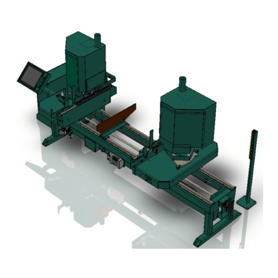
Overview of the 979-2 Miter Trim Saw System Overview of the 979-2 Miter Trim Saw System model is designed to cut casing KVAL 979-2 Miter Trim Saw for doors and windows at rates up to 25 pieces per minute for softwood material. Saws pivot between either 0- or 45- degree positions. -
Page 9: About This Manual
Overview of the 979-2 Miter Trim Saw System About this Manual This manual is part of a package delivered with the machine line. Integration Package includes the following: includes the following: Operation Manual Chapter Title Description Introduction Descriptions of Machine Line and Safety Information. -
Page 10: Safety First
Training Ensure that all employees who operate this machine are aware of and adhere to all safety precautions posted on the machine and are trained to operate this machine in a safe manner. KVAL 979-2 Service Manual... - Page 11 Before performing any mainte- nance or repairs on this machine turn off the main air disconnect. Lockout and tagout this connection. See “Lockout Tagout Procedure” on page 1-9. KVAL 979-2 Service Manual...
- Page 12 Tagout, or Lockout the electrical and air pressure systems. This should be done in accordance with applicable state and/or federal code requirements. Laser Warnings On some machines, laser indicators are used to set boundaries. Follow the manufacturers safety precautions. KVAL 979-2 Service Manual...
- Page 13 Follow Your Company’s Safety Procedures In addition to these safety guidelines. Your company should have on-site and machine specific safety proce- dures to follow. KVAL 979-2 Service Manual...
-
Page 14: Lockout-Tagout Guidelines
O..OFF! Shut off all power sources and isolating devices P..Place lock and tag E..ENERGY: Release stored energy to a zero-energy state R ..Recheck controls and test to ensure they are in the “OFF” state KVAL 979-2 Service Manual... -
Page 15: Lockout Tagout Procedure
Turn Switch to the Lock and Tagout Insert Lock into hole. OFF position Note: When multiple people are working on the machine, each person needs to have a lock on the handle in the extra holes provided. KVAL 979-2 Service Manual... -
Page 16: Lockout Tagout Air Supply
The lock and tag can now be removed (only by the person(s) who placed them), and the machine can be re-energized. The tags must be destroyed and the locks and keys returned to the lockout center. 1-10 KVAL 979-2 Service Manual... -
Page 17: Zero-Energy To Start-Up
Replace Guards Replace all equipment guards. If part of equipment cannot be properly adjusted after start-up with guard on, contact the Service team. See “Getting Help from Kval” KVAL on page 1-13. Check Controls Confirm that all switches are in the “OFF” position. Please be advised that some com- ponents of the machine may start automatically when energy is restored. - Page 18 Be sure to follow the P-R-O- P-E-R lockout/tagout procedures, and that those around you do also. Close the Cage Gate Verify all cage gates are securely closed. Ensure all safety protocols are in effect. 1-12 KVAL 979-2 Service Manual...
-
Page 19: Getting Help From Kval
• Outside the U.S. and Canada, call (707) 762-7367 or fax (707) 762-0485 • Email address is service@Kvalinc.com • Hours: 6:00 AM to 4:00 PM Pacific Standard Time, Monday through Thursday 6:30 AM to 1:30 PM Pacific Standard Time, Friday 1-13 KVAL 979-2 Service Manual... -
Page 20: Kval Return And Warranty Policy
Kval Return and Warranty Policy Kval Return and Warranty Policy goal is to provide customers with high quality products. If, for any reason, you are not Kval's completely satisfied with your purchase, please contact us at: Email: parts@kvalinc.com +1 (800) 553-5825 Phone: •... -
Page 21: Customer Errors
Kval Return and Warranty Policy Customer Errors If the item is to be returned due to customer ordering error, the customer must return the item to or the shipper of origin at its expense. A 15% restocking fee may apply to manufactured... - Page 22 Kval Return and Warranty Policy 1-16 KVAL 979-2 Service Manual...
-
Page 23: Safety Sign-Off Sheet
Note: It is recommended you make a copy of this sheet for new operators. If a copy is needed, you may download a PDF at the website ( KVAL http://www.kvalinc.com You may also contact our Service Department at (800) 553-5825 or email at service@kvalinc.com. 1-17 KVAL 979-2 Service Manual... - Page 24 Safety Sign-Off Sheet 1-18 KVAL 979-2 Service Manual...
-
Page 25: Maintenance Of The 979-2
This chapter describes preventative maintenance steps for . The content is geared to KVAL 979-2 guide technicians to keep a regular maintenance schedule for your KVAL machine. Keeping your KVAL machine maintained is an important piece for successful operation of your production pro- cess. -
Page 26: Maintenance Schedule
Inspect all airlines for kinks or rubbing. Inspect Refill all lubricators. Replace fluid if milky or discolored. Use ab ISO 32 stan- Lubricate dard hydraulic oil (KVAL part# SYS-LUBEG). Grease ball screw bearings (if applicable). Lubricate Clean all bearing shafts with clean, dry cloth. - Page 27 Inspect all nuts and bolts for tightnesses Tighten is necessary. Inspect Check that there is a smooth transition with a door feeding into and out of Inspect machine. Backup computer software. Back-up Wash filter and lubricator bowls with soapy water. Clean KVAL 979-2 Service Manual...
-
Page 28: Maintenance No-Goes
• Do not adjust air PSI above or below factory settings • Do not adjust any and all flow controls from factory settings • Do not remove shim stock KVAL 979-2 Service Manual... -
Page 29: Lubrication Schedule
Assembly Lubrication Type Linear Bearing Pillow Block Bearing Every 250 Hours of Machine Operation Idler Shaft Dura-Lith Grease (KVAL P/N Lube EP-2) Flange Block Bearing Ball Screw Every 80 Hours of Machine Operation Tapered Bearing Once 4 X a Year... -
Page 30: Lubrication Requirements
Closed Pillow Block Hub Style Opened Pillow Block parallel perpendicular mount Greasing Approximatively 1 Gram (one pump from grease gun) of Dura-Lith Grease (KVAL P/N: Lube EP-2). Every 250 hours of operation. Pillow Block Bearings FIGURE 2- 1. KVAL 979-2 Service Manual... -
Page 31: Flange Bearing Housings
Flange Greasing Housings Bearing Approximatively 1 Gram (one pump from grease gun) of Dura- Lith Grease (KVAL P/N: Lube EP-2). Every 250 hours of oper- ation. Flange Bearings FIGURE 2- 2. Ball Rail Bearing are linear bearings that are attached to positioning rails. In most cases, the bear- Ball Rail Bearings ings are attached to assemblies to move them in the X,Y, or Z direction. -
Page 32: About Taper Bearings
To identify a , look at the enclosure and verify there are seals Tapered Bearing Housing between the screw and the housing. Tapered Bear- ing Housing Tapered Bearing Seals Tapered Bearing Housing FIGURE 2- 5. KVAL 979-2 Service Manual... -
Page 33: Ball Screw Nut
The ball screw drive and the ball screw nut create very low friction coefficients resulting in a smooth, accurate, efficient movement. Greasing Approximatively 1 Gram (one pump from grease gun) of Dura-Lith Grease (KVAL P/N: Lube EP-2). Every 80 hours of operation. Ball Screw Nut Ball... -
Page 34: Lubrication Points On The 979-2
Lubrication Points on the 979-2 Lubrication Points on the 979-2 This Section illustrates lubrication points on the machine. See “Maintenance Schedule” on page 2-2 for types of lucubration and a schedule for preventive maintenance. This machine is a powerful electro-mechanical Caution ... -
Page 35: Lubrication Points Heads
Lubrication Points on the 979-2 Lubrication Points Heads For lubrication schedule information, see “Lubrication Schedule” on page 2-5. Figure 2- 9 below shows the X,Y, and Z axis bearings of the from the back section viewpoint. The bear- Cutter Head ings are color coded for easy identification. -
Page 36: Replacing The Chipout Block
Secure the new block with the 2 set screws. Re-attach the Carriage Head covers. Reverse the Lockout Tagout process. Make sure that the machine safe. Burn in the Block Remove Chipout Block 2 screws each 2-12 KVAL 979-2 Service Manual... -
Page 37: Process To Burn In A Chipout Block
Reverse Lockout Tagout. Make sure that the machine safe. Home machine on start-up Example of a Newly Burned in Chipout Block The figure below shows a newly burned in Chipout Block. Example of a burned-in Chipout Block. 2-13 KVAL 979-2 Service Manual... -
Page 38: Mechanical Adjustments
Failure to do so can result in damage to equipment and/or serious injury to person- nel. 979-2 Guard Placements and Purpose The following information gives a description of the mechanism being guarded, and the hazard being guarded against. -
Page 39: Feed Dog Adjustment Procedure
Holding the right angle of a T-Square against the Fixed Head Dog plate, adjust the forward feed stops so both the fixed head middle feed dog and movable head feed dog and the alignment mark all line up. 2-15 KVAL 979-2 Service Manual... - Page 40 Manually Pull both movable and fixed head dog plates agents the Feed Reverse stops Adjust the Feed Reverse stop for a gap of 8 15/16” between the forward edge of both Feed Dog Plates and the Feed Forward Stop. 2-16 KVAL 979-2 Service Manual...
- Page 41 Mechanical Adjustments 8 15/16'' Feed Reverse Feed Forward Feed Dog Plate Stop Stop Reinstall the inside covers Remove Lockout /Tagout Continue production 2-17 KVAL 979-2 Service Manual...
-
Page 42: Description Of Air Input System
Once you have a steady flow, tighten knob back down until you have one drop per every other cycle. Drop will form at end of cane shaped tube visible inside glass. 2-18 KVAL 979-2 Service Manual... -
Page 43: Air Line Without Lubricator
The air input system takes in shop air and supplies clean dry air (CDA). Clean Dry Air (CDA) to Shop Air Air Blow Off Input Air On- Off Knob Muffler Filter (purge) Pressure Gauge with adjust Air Distribution Block Air Filter without Lubricators FIGURE 2- 11. 2-19 KVAL 979-2 Service Manual... - Page 44 Description of Air Input System 2-20 KVAL 979-2 Service Manual...
-
Page 45: Troubleshooting The 979-2
Typical Positioning Systems .................page 3-4 Troubleshooting Basics ................. page 3-7 Using Sensors to Trouble Shoot ..............page 3-7 Location of Sensors on 979-2 ................. page 3-8 Troubleshooting Electrical Problems ............. page 3-9 If the Power Stops During Normal Operation ..........page 3-9 Troubleshooting with the Status Light Panel ..........page 3-10... -
Page 46: About Motion Control
There are four parts to a motion control system: Position Feedback (Optional) Positioning Instructions (Optional) Positioning User Interface Controller Load System Translated Force Positioning Instructions Process Complete OK to move Machine’s Other Subsystems FIGURE3- 12. KVAL 979-2 Service Manual... - Page 47 • Moves the load. Examples: A motor or a pneumatic cylinder. The Position Feedback. • Provides location information to the controller. Examples: A limit switch, a photo eye, or ferrous eye, a resolver or an encoder KVAL 979-2 Service Manual...
-
Page 48: Typical Positioning Systems
Output Should measure Relay Line Voltage here Power Input Control Contactor (Coil) Input 120 VAC Power Output Control Circuit Common DC - Thermal OverLoad Should measure Line Voltage here Motor Common contactor Block diagram FIGURE 3-13. KVAL 979-2 Service Manual... - Page 49 Power Input STR (Revers 2) Run Light Motor should be ON Drive Power Output SD (COMMON) Should display the Motor Frequency Should measure Line Voltage here Control Circuit Common Motor Common Motor Drive Control FIGURE3- 14. KVAL 979-2 Service Manual...
- Page 50 Power Input STR (Revers 2) Run Light Motor should be ON Drive Power Output SD (COMMON) Should display the Motor Frequency Should measure Line Voltage here Control Circuit Common Motor Common Pneumatic Block Diagram FIGURE3- 15. KVAL 979-2 Service Manual...
-
Page 51: Troubleshooting Basics
• Check output voltages of the sensors in the active mode. The voltage should effec- tively equal 0 VDC • Check the output voltages of the sensors in inactive mode.The voltage should effec- tively equal 24 VDC KVAL 979-2 Service Manual... -
Page 52: Location Of Sensors On 979-2
Metal-Sensor: Optical Sensor: Open Limit Right Board Straight Right Head Switches: 45 degrees Saw Retracted Metal-Sensor: Saw Extended Home Kerf Saw Retracted Kerf Saw Extended Metal-Sensor: Close Limit Location of Sensors Top View 979-2 FIGURE3- 16. KVAL 979-2 Service Manual... -
Page 53: Troubleshooting Electrical Problems
Observe the disconnect switches. Look for loose or broken wires at the disconnect then at all of the components. Check for continuity of all fuses with an OHM meter. (Fuses need to be removed from the bottom side of the fuse holder before measuring the fuses) KVAL 979-2 Service Manual... -
Page 54: Troubleshooting With The Status Light Panel
The Status Light Panel is located on the Electrical Panel. All six lights are illuminated when the system is in proper working order. The lights turn on in a sequence and will stop at the point where a fault is first detected. 3-10 KVAL 979-2 Service Manual... - Page 55 STEP 4: Stop (Amber) If light is OFF go to item on page 3-13. STEP 5: Start (Amber) If light is OFF go to item on page 3-14. STEP 6: 24VDC (Green light is OFF go to item on page 3-14. 3-11 KVAL 979-2 Service Manual...
- Page 56 If no power on the output side, and there is power going into the top of the Control Transformer, replace the Control Transformer. If there is power at the Control Transformer, check the wiring of the black and white wire going from the Control Transformer to the 110 VAC Terminal Strip. 3-12 KVAL 979-2 Service Manual...
- Page 57 Start button. If no voltage, check the Stop button to make sure it is all the way out and not stuck in, then check the contact to make sure it is closed. If still no voltage, check the wiring. 3-13 KVAL 979-2 Service Manual...
- Page 58 Check for +24VDC at between any –DC and +DC terminal on the DC Terminal block. Reinstall the (+ 24V positive) wires one by one, checking for +24VDC after installing each. If at any point no voltage is found trace the last reinstalled wire and check for shorts. 3-14 KVAL 979-2 Service Manual...
-
Page 59: About Vfd Troubleshooting
Kval” on page 1-13 VFD Reset Buttons VFD Reset Buttons FIGURE 3- 17. Note: The number of reset buttons depends on the machine type and option. The fig- ure above shows a machine with 11 VFDs 3-15 KVAL 979-2 Service Manual... -
Page 60: Troubleshooting The Air Cylinders
Check the flow controls to see that they are adjusted correctly and to the proper specifications. Check for any obstructions to the cylinders such as Manual over- ride button screws or a misplaced tool etc. FOLLOW ALL SAFETY GUIDELINES AND SIGNS DURING THIS PROCESS. 3-16 KVAL 979-2 Service Manual... -
Page 61: Adjusting Cylinder Extension Speed
When the air leak stops or weakens it usually means that one or more of the cylinders that the solenoid is operating are faulty. Adjusting Cylinder Extension Speed: Adjusting Cylinder Retraction Speed: 3-17 KVAL 979-2 Service Manual... -
Page 62: Adjusting Limit Switches
Use the set screw on the limit switch arm and adjust the arm to acti- vate at the desired degree of rotation (see illustrations below). How to Adjust a Switch FIGURE3- 18. 3-18 KVAL 979-2 Service Manual... - Page 63 2-5 pillow block bearing, maintenance schedule 2-5 power lock out procedure 1-9 power up troubleshooting 3-9 safety guidelines 1-4 Safety Sign Off Sheet Safety Concerns 1-17 sensors descriptions 3-7 location on frame 3-8 troubleshooing 3-7 979-2 Service Manual...
- Page 64 Index 979-2 Operation Manual...
- Page 66 Customer Service Contacting KVAL Phone and Fax: Mailing address: In the U.S and Canada, call (800) 553-5825 or fax Customer Support Department (707) 762-0485 Kval Incorporated Outside the U.S. and Canada, call (707) 762-7367 825 Petaluma Boulevard South or fax (707) 762-0485 Petaluma, CA 94952 Email: service@kvalinc.com...
Need help?
Do you have a question about the 979-2 and is the answer not in the manual?
Questions and answers