Kval 979-2 Operation And Service Manual
Miter trim saw system
Hide thumbs
Also See for 979-2:
- Operation manual (108 pages) ,
- System reference manual (102 pages) ,
- Service manual (66 pages)

Related Manuals for Kval 979-2


Summary of Contents for Kval 979-2
- Page 1 Innovation, Quality & Honesty 979-2 Miter Trim Saw System Operation and Service Manual Published 5/24/2019...
- Page 2 Proprietary Notice This Manual is confidential and contains proprietary information and intellectual property of KVAL Inc., and is to be used solely by Customer as an operating manual for KVAL Inc. machines. Neither this Manual nor any of the information contained herein may be reproduced or disclosed under any circumstances without the express written permission of KVAL Inc.
- Page 3 KVAL 979-2 Operation/Service Manual Your Feedback is Welcome: To help us design products that make your job easier and your business more successful, we'd like to gain your perspective about your user experience with our product - that is, the manual, the machinery, the software, etc.
- Page 4 KVAL 979-2 Operation/Service Manual...
-
Page 5: Table Of Contents
Table Of Contents Introduction to the 979-2 Miter Trim Saw System Chapter 1 Chapter 1 at a Glance.............. 1-1 Overview of the 979-2 Miter Trim Saw System......1-2 About this Manual .................1-3 Safety First!................1-4 Safety Sheet Sign-Off Sheet..............1-4 Safety Terminology of Labels..............1-4 Safety Guidelines..................1-4... - Page 6 Quick Start ................2-12 Powering Operations for the 979-2.......... 2-14 How to Power Up the 979-2..............2-14 Home the 979-2 ..................2-15 How to Power Down the 979-2 ............2-16 Emergency Shutdown and Recovery ..........2-16 About Modes..................2-17 Mechanical Set Up..............2-18 Description of User Interface Screens ........2-20 Screen Selection Menu Map...............2-20...
- Page 7 About Taper Bearings ................4-8 Tapered Bearing Housings ..............4-8 Ball Screw Nut ..................4-9 Ball Screw Drive Assembly..............4-9 Pulley and Idler Shafts................4-10 Lubrication Points on the 979-2 ..........4-11 Lubrication Points Heads..............4-12 Replacing the Chipout Block............ 4-13 Replacing Saw Blades............. 4-14 Remove the Saw ................4-14 Description of Air Input System ..........
- Page 8 979-2 Miter Trim Saw System...
-
Page 9: Chapter 1 At A Glance
CHAPTER 1 Introduction to the 979-2 Miter Trim Saw System This chapter provides an overview of the KVAL 979-2 Miter Trim Saw System and important safety information to follow when operating the machine. Chapter 1 at a Glance Chapter 1 at a Glance .................. -
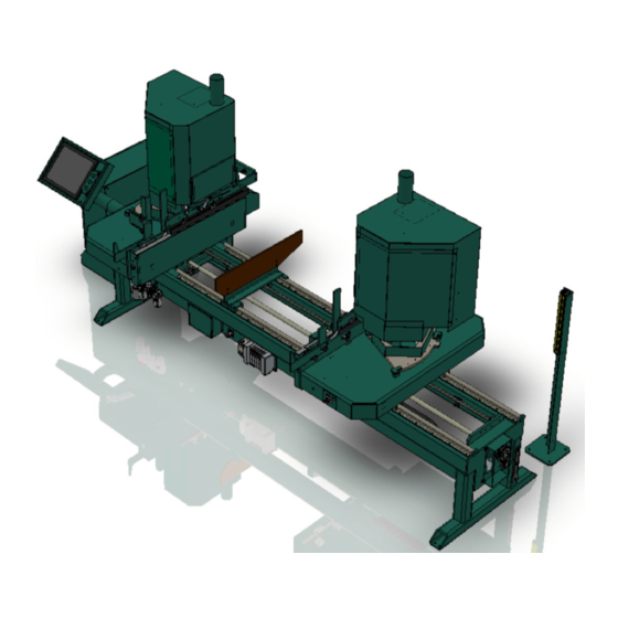
Page 10: Overview Of The 979-2 Miter Trim Saw System
8 CFM. The 979-2 will miter side casing, with a 90 degree trim on the bottom, up to 98” long on the short side of the miter. Head casing, mitered on both ends, can be cut as short as 12-3/8” measured on the short side. -
Page 11: About This Manual
Overview of the 979-2 Miter Trim Saw System About this Manual This manual contains operation information and service and maintenance information. It includes identification of machine assemblies, power-up and power-down steps, and informa- tion about using the user interface. The Troubleshooting and Maintenance sections are directed toward qualified service technicians TABLE 1- 1. -
Page 12: Safety First
See “Safety Sign-Off Sheet” on page 1-16. Safety Terminology of Labels In addition to the nameplate, KVAL machines may have other warning labels or decals that pro- vide safety information to operators. Safety labels should be clearly visible to the operator and must be replaced if missing, damaged, or illegible. - Page 13 Before performing any mainte- nance or repairs on this machine turn off the main air disconnect. Lockout and tagout this connection. See “Lockout Tagout Procedure” on page 1-9. KVAL 979-2 Operation/Service Manual...
- Page 14 This should be done in accordance with applicable state and/or federal code requirements. Laser Warnings On some machines, laser indicators are used to set boundaries. Follow the manufacturers safety precautions. KVAL 979-2 Operation/Service Manual...
- Page 15 Safety First! Compliance with Codes and Regulations KVAL advises that you request an on-site state safety review of your installation of this machine. This is to ensure conformance to any additional specific safety and health regula- tions which apply in your geographic area.
-
Page 16: Lockout-Tagout Guidelines
O..OFF! Shut off all power sources and isolating devices P..Place lock and tag E..ENERGY: Release stored energy to a zero-energy state R ..Recheck controls and test to ensure they are in the “OFF” state KVAL 979-2 Operation/Service Manual... -
Page 17: Lockout Tagout Procedure
Turn Switch to the Lock and Tag out Insert Lock into hole. OFF position Note: When multiple people are working on the machine, each person needs to have a lock on the handle in the extra holes provided. KVAL 979-2 Operation/Service Manual... -
Page 18: Lockout Tagout Air Supply
The lock and tag can now be removed (only by the person(s) who placed them), and the machine can be re-energized. The tags must be destroyed and the locks and keys returned to the lockout center. 1-10 KVAL 979-2 Operation/Service Manual... -
Page 19: Zero-Energy To Start-Up
Replace Guards Replace all equipment guards. If part of equipment cannot be properly adjusted after start-up with guard on, contact the KVAL Service team. See “Getting Help from KVAL” on page 1-13. Check Controls Confirm that all switches are in the “OFF”... - Page 20 Be sure to follow the P-R-O- P-E-R lockout/tagout procedures, and that those around you do also. Close the Cage Gate Verify all cage gates are securely closed. Ensure all safety protocols are in effect. 1-12 KVAL 979-2 Operation/Service Manual...
-
Page 21: Getting Help From Kval
Ask about this procedure when calling are service team Product Return Procedure If you’ve contacted Kval for help and it is determined that a return is necessary, use the procedure below to return the machine or part. - Page 22 • With what equipment is the unit interfaced? • What was the application? • What was the system environment (temperature, spacing, contaminants, etc.)? Call Kval customer support for a Return Material Authorization (RMA). When you call: • Have the packing slip or invoice numbers available.
- Page 23 Getting Help from KVAL Page Intentionally Left Blank 1-15 KVAL 979-2 Operation/Service Manual...
-
Page 24: Safety Sign-Off Sheet
Note: It is recommended you make a copy of this sheet for new operators. If a copy is needed, you may download a PDF at the KVAL website (http://www.kvalinc.com). You may also contact our Ser- vice Department at (800) 553-5825 or email at service@kvalinc.com. - Page 25 Safety Sign-Off Sheet 1-17 KVAL 979-2 Operation/Service Manual...
-
Page 26: Operation Of The
CHAPTER 2 Operation of the 979-2 This chapter describes components, assemblies, and the user interface of the KVAL 979-2 Miter Trim Saw System. The content is geared to help operators understand the basic operation of the 979-2. Chapter 2 at a Glance Operator’s Tour... -
Page 27: Operator's Tour
Operator’s Tour Operator’s Tour This section takes you on a tour of the 979-2 Miter Trim Saw System machine. Electrical Panel Operator’s Station Left or Fixed Head Out-Feed In-Feed Safety Curtain Hopper, Staging area, and Feed-In Foot Pedal: Stop Feed... -
Page 28: In-Feed Section
If the hopper is stacked the product will feed through automatically.(Or the quantity set on the main screen) Start Sequence • Press the left pedal to stop the machine. This acts like an E-Stop. KVAL 979-2 Operation/Service Manual... -
Page 29: Operators Station
FIGURE 2- 3. Operators Station (Small Platform Screen) A reduced size screen has been added to the 979-2 (Start SN 17-146-061). The menu choices and controls are similar but have changes in format. See “Screen Selection Menu Map (Small Plat- form Screen)”... -
Page 30: The Starts Saws Button
Never mechanically bypass the Safety Curtain or enter the cutting area avoiding the Safety Curtain. Serious injury could occur. Out Feed Area: Fin- ished Product is fed out of the machine Electrical Safety Curtain Safety Curtain Panel Out-Feed Key Parts FIGURE 2- 5. KVAL 979-2 Operation/Service Manual... -
Page 31: About The Electrical Panels
High Voltage is present in this panel at the top of the Three Phase Input even with the disconnect off. If working on the panel, follow the safety protocol as described in Chapter 1. The 979-2 has a Main Electrical Panel. Figure 2- 7 below, is an overview of the location of assem- blies in the panel •... -
Page 32: Main Electrical Panel (Before Vpn)
Input / Output Terminals 110 V / 24 V Terminals High Voltage Section Control Trans- former Contactor and Over- VFD Section load Circuit Servo Drive Overview of Main Electrical Panel and High Frequency Panel FIGURE 2- 7. KVAL 979-2 Operation/Service Manual... -
Page 33: About Using The Vpn
The VPN is an industrial remote access router that is designed to offer remote access, across the Internet, to the 979-2. KVAL technicians can troubleshoot machines, debug the PLC program while the operator runs the machine. The VPN works in the background. -
Page 34: About The Safety Curtain
Product Output: Machine will stop if barrier is broken. Restart the machine to continue Emitter Receiver Receiver Emitter Emitter Receiver Breaking of any beam Machine in operation stops the machine KVAL 979-2 Operation/Service Manual... -
Page 35: Description Of The Six Light Panel
Description of the Six Light Panel Description of the Six Light Panel The six lights on this panel indicate the status of the 979-2 system. The Sequence that the lights activate is as follows: Control Power Overload Relay E-Stop Stop... -
Page 36: About Sensors
Description of the Six Light Panel About Sensors On the 979-2, sensors provide input to the PLC as part of the automation of the cutting process. It is important to keep the sensors cleaned and aligned to keep the process running smoothly. There are two classifications of sensors on the 979-2------Photo Electronic and Inductive Proximity Sen- sor. -
Page 37: Quick Start
Note: Follow the same steps in the Quick Start below. See “Running a Reference Cut” on page 2-27 Ensure factory air is present at the machine and the 979-2 main air supply valve is turned on. Power up the 979-2. - Page 38 (Button displays Saws Active Start production by pressing the Start Sequence right the foot pedal. If finished with production and shutting the machine down, see “How to Power Down the 979-2” on page 2-16 2-13 KVAL 979-2 Operation/Service Manual...
-
Page 39: Powering Operations For The 979-2
Powering Operations for the 979-2 Powering Operations for the 979-2 This section describes how to power up and to power down the 979-2. Powering up the system includes: • Applying power to the entire system • Starting the Control Circuit Powering down the system includes: •... -
Page 40: Home The 979-2
The 979-2 must go through a homing routine before any operations are performed. The homing routine sets a zero reference from which the 979-2 measures its movement and cutting process. If power is lost or the 979-2 is re-set, the homing routine must be performed again to reset the zero reference... -
Page 41: How To Power Down The 979-2
Switch the green switch to the CONTROL TRANSFORMER OFF position. KVAL also recommends that you turn the disconnect switch on the electrical cabinet to OFF; this helps reduce possible damage resulting from power surges from electri- cal storms. Emergency Shutdown and Recovery There are emergency shutdown (E-Stop) switch located at key points around the machine. -
Page 42: About Modes
Powering Operations for the 979-2 About Modes The four different cut modes are illustrated below. See “About Adjusting Each Cut Mode” on page 2-30 for information about selecting the dimensions for the cut. Right Head Left Head 45 deg - 45 deg... -
Page 43: Mechanical Set Up
Adjust both back hopper stops for a hopper width of roughly 1/8-inch larger than the stock. Adjust both front hopper stop's height to clear the stock by roughly 1/8-inch. Front Hopper Stop Rear Hopper Stop Note: Use a 1/2'' wrench to Adjust the Bolts Adjustment Bolts for Height 2-18 KVAL 979-2 Operation/Service Manual... - Page 44 NOTE: Wide jamb mode has better clamping ability than narrow jamb mode; tighter clamping produces cleaner saw cuts. Wide jamb mode can be used on narrow stock. The disadvantage is that wide jamb mode is slower by about 3 boards per minute. 2-19 KVAL 979-2 Operation/Service Manual...
-
Page 45: Description Of User Interface Screens
This section describes the user interface screens. The user interface allows the operator to use a touch screen to control the trim cutting process, auto-run, manually run the trim, store trim pro- files, and use diagnostics to help troubleshoot the 979-2. Screen Selection Menu Map Below are the menu selections for the 979-2 See “Main Screen”... -
Page 46: Screen Selection Menu Map (Small Platform Screen)
Description of User Interface Screens Screen Selection Menu Map (Small Platform Screen) Below are the menu selections for the 979-2 using a small platform touch screen (Start SN 17-146-061).The definitions of the buttons are the same. Changes in menu operation is slightly changed. The main change is there are more jump pages to utilize. -
Page 47: Machine Feed Back
In the ON position the setup mode is active the saws will be OFF. In the OFF position the setup mode is not active and the Saws will be ON. These keys may be taken out in the off position. 2-22 KVAL 979-2 Operation/Service Manual... -
Page 48: Main Screen
Description of User Interface Screens Main Screen The Main Screen is also the startup screen for the 979-2. From this screen, all the basic user inter- face controls are available to run a cut on a trim board. Jump Buttons Main Screen FIGURE 2- 11. - Page 49 The machine is now primed to perform. See “Description of User Interface Screens” on page 2-20 for full operation steps. To assign a preset to the button: See See “About Assigning a Pre-set” on page 2-31 for more information 2-24 KVAL 979-2 Operation/Service Manual...
- Page 50 The process is: Enter casing length desired. Set the desired quantity. The machine will stop after the quantity is reached. (0 quantity will keep running until operator stops the machine) Select the Button. Load the Cut Parameters 2-25 KVAL 979-2 Operation/Service Manual...
- Page 51 SAWS ACTIVE During machining it is recommended to use this button to shutdown the saws. This will save time of booting up the machine. See “How to Power Down the 979-2” on page 2-16 if shutting down for the night.
-
Page 52: About The Setup Screens
Use this information as a guide to help input the directional data in the calibration routines. = Reverse Direction X Axis Servo Motor Green = Forward Direction 2-27 KVAL 979-2 Operation/Service Manual... -
Page 53: Entering Calibration Data
If it is correct, go back to the calibration screen and click to combine Combine with Offset offset and base to complete the calibration. Click the button to clear any incorrect number in the Offset box. Note: Clear Offset 2-28 KVAL 979-2 Operation/Service Manual... -
Page 54: About The Machine Calibration Screen
• Individual parameters for each cut mode. • System wide or all cut modes as a set. Miter Stop Adjustments are an Optional choice for machines with Miter Option Setup Menu FIGURE 2- 12. 2-29 KVAL 979-2 Operation/Service Manual... - Page 55 If a discrepancy is observed on the miter stops, use this menu to adjust stop positions. About Adjusting System Cut Modes If all the lengths are out of specification the same amount. Use this menu to adjust the cutter heads. 2-30 KVAL 979-2 Operation/Service Manual...
-
Page 56: About Assigning A Pre-Set
Enter the length in either decimal or fractional measure- ments. Select the button. Save Small Plat- form Screen Select the button to go Main back to the main menu. The previ- ously selected button will have the title and length. 2-31 KVAL 979-2 Operation/Service Manual... -
Page 57: About Manual Operation And Chipout Routine
Open Button until the Saw Car- riage moves to the desired loca- tion. Press the Exit Application button to close the user screen and return to the Main Screen Manual Operation Screen FIGURE 2- 13. 2-32 KVAL 979-2 Operation/Service Manual... - Page 58 Release to detract After burn-in is completed, release the Start Saws saw away from and release the Button Chipout Routine Software chipout Button Reverse Lockout Tagout. Home machine on start-up Example of a burned-in chipout block. 2-33 KVAL 979-2 Operation/Service Manual...
-
Page 59: Diagnostic Screen
The top line will have the most current routine that is running. If the machine issue can not be resolved, call KVAL Inc. (1- 800-553-5825). Have any error code that is displayed, ready to give the KVAL representative. - Page 60 Notes:...
-
Page 61: Chapter 3 System It Administration
CHAPTER 3 System IT Administration This chapter describes the KVAL 979-2 controller. The controller is an on board computer that supplies the user interface and controls the operation of the machine. With the controller, KVAL can remotely help troubleshoot your machine. - Page 62 Support will be able to access your machine through your company’s Intranet and help solve any issues that may occur. Connection to the Intranet is achieved by interfacing with the 979-2 con- troller. The location of the Intranet connection is identified in the figure below (RJ45 to Intranet.) About the 979-2 Computer ®...
- Page 63 It is recommended to set up a back-up schedule to save your data on a regular occurrence. The KVAL service team would be happy to help. If any questions occur, contact our service team at (800) 553-5825 or at www.kvalinc.com.
- Page 64 System IT Administration KVAL 979-2 Operation/Service Manual...
-
Page 65: Maintenance Of The
CHAPTER 4 Maintenance of the 979-2 This chapter describes preventative maintenance steps for KVAL 979-2. The content is geared to guide technicians to keep a regular maintenance schedule for your KVAL machine. Keeping your KVAL machine maintained is an important piece for successful operation of your production pro- cess. -
Page 66: Maintenance Schedule
Maintenance Schedule Maintenance Schedule KVAL recommends the following maintenance schedule to ensure that the machine operates properly. Cycles refers to the quantity of processed doors. Cleaning curtails build up of sawdust and grime which causes issues with the operation of the machine. Inspecting, finds issues before they become problems. - Page 67 Inspect all nuts and bolts for tightnesses Tighten is necessary. Inspect Check that there is a smooth transition with a door feeding into and out of machine. Back-up Backup computer software. Clean Wash filter and lubricator bowls with soapy water. KVAL 979-2 Operation/Service Manual...
-
Page 68: Maintenance No-Goes
• Do not adjust air PSI above or below factory settings • Do not adjust any and all flow controls from factory settings • Do not remove shim stock KVAL 979-2 Operation/Service Manual... -
Page 69: Lubrication Schedule
Lubrication Schedule Lubrication Schedule KVAL recommends the following lubrication schedule to ensure that the machine operates prop- erly. Recommended Lubrication Schedule TABLE 4-1. Type of Recommended Schedule Recommended Assembly Lubrication Type Linear Bearing Pillow Block Bearing Every 250 Hours of Machine Operation... -
Page 70: Lubrication Requirements
Closed Pillow Block Hub Style Opened Pillow Block parallel perpendicular mount Greasing Approximatively 1 Gram (one pump from grease gun) of Dura-Lith Grease (KVAL P/N: Lube EP-2). Every 250 hours of operation. Pillow Block Bearings FIGURE 4-16. KVAL 979-2 Operation/Service Manual... -
Page 71: Flange Bearing Housings
X,Y, or Z direction. Greasing Ball Rail Bearing Approximatively 1 Gram (one pump from grease gun) of Dura-Lith Grease (KVAL P/ Every 250 hours N: Lube EP-2). of operation. Ball Rail Bearings FIGURE 4-18. KVAL 979-2 Operation/Service Manual... -
Page 72: About Taper Bearings
The taper bearings differ from other machine bearing assemblies, in that they are in a sealed envi- ronment. To identify a , look at the enclosure and verify there are seals Tapered Bearing Housing between the screw and the housing. Tapered Bearing Housing Tapered Bearing Seals Tapered Bearing Housing FIGURE 4-20. KVAL 979-2 Operation/Service Manual... -
Page 73: Ball Screw Nut
Ball Screw Drive Assembly. Ball Screw Nut Recommended every 80 Hrs Servo Motor Pillow Block (Hub Style Recommended every 250 Hrs Tapered Bearing Housing Once a Year Ball Screw Drive Assembly FIGURE 4-22. KVAL 979-2 Operation/Service Manual... -
Page 74: Pulley And Idler Shafts
Breakout of Pulley Assembly Pulley in Action Grease IN Note: It is important not to overfill the Idler Shaft. Avoid get- ting excess grease on the belts Grease Out Idler Shaft 4-10 KVAL 979-2 Operation/Service Manual... -
Page 75: Lubrication Points On The 979-2
Lubrication Points on the 979-2 Lubrication Points on the 979-2 This Section illustrates lubrication points on the machine. See “Maintenance Schedule” on page 4-2 for types of lucubration and a schedule for preventive maintenance. IMPORTANT: Aways Follow Lockout Tagout Procedures when working on this machine. -
Page 76: Lubrication Points Heads
Lubrication Points on the 979-2 Lubrication Points Heads Identify zerk fittings and apply EP-2 grease. Find the X, Y and Z axis rails to identify bearings. Some bearings may be difficult to get access to. Use an extender to reach tight areas. Make sure... -
Page 77: Replacing The Chipout Block
Remove the 2 set screws that secure the chipout block. Lift the old block out of the holder and replace with new one. Secure block with set screws. Re-assembly the covers to the Fixed Head and Movable Head. 4-13 KVAL 979-2 Operation/Service Manual... -
Page 78: Replacing Saw Blades
Remove the Saw Perform Lockout Tagout Remove Front Cover Loosen Knob on the and Open it. Access Cover Access Cover Remove Cylinder Assembly lay down out of the way Remove 2 bolts Cylinder Assembly Move Cylinder Aside 4-14 KVAL 979-2 Operation/Service Manual... - Page 79 Note: Ensure the Nut is placed with the flat side against the blade (See Inset) Open End Wrench Allen Wrench Outer Saw Washer Nut: Ensure side pictured is against the blade Follow the in reverse to finish the assembly. Steps 4-15 KVAL 979-2 Operation/Service Manual...
-
Page 80: Description Of Air Input System
Description of Air Input System Description of Air Input System There are two types of air inputs on KVAL machinery. Not all machines have lubricator option installed. Check your machine or Air prints to verify installation. Air Input with Lubrication The air input system takes in shop air and supplies clean dry air (CDA) and lubricated air to the machine. -
Page 81: Air Line Without Lubricator
The air input system takes in shop air and supplies clean dry air (CDA). Shop Clean Dry Air (CDA) t Air Blow Off Input Air On- Off Knob Muffler Air Distribution Block Pressure Gauge with adjust Filter (purge) Air Filter without Lubricators FIGURE 4-26. 4-17 KVAL 979-2 Operation/Service Manual... -
Page 82: Mechanical Adjustments
Mechanical Adjustments The 979-2 is a powerful electro-mechanical motion Caution control system. If servicing the 979-2 follow the safety guidelines described in this manual. Failure to do so can result in damage to equipment and/or seri- ous injury to personnel. - Page 83 Mounted directly over the kerf blade(s) on both kerf routers located on either end of the 979-2. The kerf blade guard is designed to protect the operator from the kerf blade, whether or not the machine is operating. The kerf blade guard protects the operator from possible amputation, eye injury from air- borne dust and wood particles, and cuts.
-
Page 84: Feed Dog Adjustment Procedure
Head For- Stop ward Feed Stop Fixed Head Movable Head Dog Plate Dog Plate Feed Fixed Head Movable Head Alignment Feed Middle Mark Fixed Head Mid- Fixed Head T-Square dle Feed Dog Plate Movable Head Plate 4-20 KVAL 979-2 Operation/Service Manual... - Page 85 Adjust the Feed Reverse stop for a gap of 8 15/16” between the forward edge of both Feed Dog Plates and the Feed Forward Stop. 8 15/16'' Feed Reverse Feed Forward Feed Dog Plate Stop Stop Reinstall the inside covers Remove Lockout /Tagout Continue production 4-21 KVAL 979-2 Operation/Service Manual...
- Page 86 Mechanical Adjustments 4-22 KVAL 979-2 Operation/Service Manual...
-
Page 87: Troubleshooting The
Troubleshooting the 979-2 This chapter describes troubleshooting steps to help technicians solve issues that may occur with your KVAL machine. If help is needed, call or contact our KVAL Service team at (800) 553-5825 or http://www.kvalinc.com. Chapter 5 at a Glance About Motion Control .................. -
Page 88: About Motion Control
KVAL Machinery. Sequencing: Sequencing is a series of events executed in a predetermined order. Most KVAL machines use a form of sequential motion control. A typical series of events for a KVAL machine are: Move the product into position. - Page 89 • Moves the load. Examples: A motor or a pneumatic cylinder. The Position Feedback. • Provides location information to the controller. Examples: A limit switch, a photo eye, or ferrous eye, a resolver or an encoder KVAL 979-2 Operation/Service Manual...
-
Page 90: Typical Positioning Systems
Output Should measure Relay Line Voltage here Power Input Control Contactor (Coil) Input 120 VAC Power Output Control Circuit Common DC - Thermal OverLoad Should measure Line Voltage here Motor Common contactor Block diagram FIGURE 5-28. KVAL 979-2 Operation/Service Manual... -
Page 91: Common Motor Drive Control
An adjustable-speed drive is used to control the motor speed and torque by varying motor input frequency and voltage. A variable-frequency drive (VFD) is used in KVAL machinery. The figure below shows a block diagram of a typical motor drive circuit with typical voltages. -
Page 92: Typical Positioning System Pneumatic Circuit
Power Input STR (Revers 2) Run Light Motor should be ON Drive Power Output SD (COMMON) Should display the Motor Frequency Should measure Line Voltage here Control Circuit Common Motor Common Pneumatic Block Diagram FIGURE5- 30. KVAL 979-2 Operation/Service Manual... -
Page 93: Troubleshooting Basics
• Check output voltages of the sensors in the active mode. The voltage should effec- tively equal 0 VDC • Check the output voltages of the sensors in inactive mode.The voltage should effec- tively equal 24 VDC KVAL 979-2 Operation/Service Manual... -
Page 94: Location Of Sensors On 979-2
Location of Sensors on 979-2 Location of Sensors on 979-2 Figure 5- 31 below, shows the sensor and switch locations on the 979-2 The “I” designation rep- resents an input to the PLC and the “Q” designation represents an output from the PLC. -
Page 95: Troubleshooting Electrical Problems
Refer to Air and Electrical Schematics provided with delivery of the machine. Schematics are located in the Electrical Panel. If copies NOTE: are unavailable, contact the KVAL Service Department. Have model number and serial number of machine readily available. Warning The following checks require the electrical panel to be energized. -
Page 96: Troubleshooting With The Status Light Panel
The Status Light Panel is located on the Electrical Panel. All six lights are illuminated when the system is in proper working order. The lights turn on in a sequence and will stop at the point where a fault is first detected. 5-10 KVAL 979-2 Operation/Service Manual... - Page 97 STEP 4: Stop (Amber) If light is OFF go to item on page 5-13. STEP 5: Start (Amber) If light is OFF go to item on page 5-14. STEP 6: 24VDC (Green light is OFF go to item on page 5-14. 5-11 KVAL 979-2 Operation/Service Manual...
-
Page 98: Control Power Light Off
If no power on the output side, and there is power going into the top of the Control Transformer, replace the Control Transformer. If there is power at the Control Transformer, check the wiring of the black and white wire going from the Control Transformer to the 110 VAC Terminal Strip. 5-12 KVAL 979-2 Operation/Service Manual... -
Page 99: Overload Relay Light Off
Start button. If no voltage, check the Stop button to make sure it is all the way out and not stuck in, then check the contact to make sure it is closed. If still no voltage, check the wiring. 5-13 KVAL 979-2 Operation/Service Manual... -
Page 100: Start Light Off
Check for +24VDC at between any –DC and +DC terminal on the DC Terminal block. Reinstall the (+ 24V positive) wires one by one, checking for +24VDC after installing each. If at any point no voltage is found trace the last reinstalled wire and check for shorts. 5-14 KVAL 979-2 Operation/Service Manual... -
Page 101: About Vfd Troubleshooting
Service Center. See “Getting Help from KVAL” on page 1-13 . VFD Reset Buttons VFD Reset Buttons FIGURE 5- 32. -
Page 102: Troubleshooting The Air Cylinders
Check the flow controls to see that they are adjusted correctly and to the proper specifications. Check for any obstructions to the cylinders such as Manual over- ride button screws or a misplaced tool etc. FOLLOW ALL SAFETY GUIDELINES AND SIGNS DURING THIS PROCESS. 5-16 KVAL 979-2 Operation/Service Manual... -
Page 103: Adjusting Cylinder Extension Speed
It might be necessary to call in a specialist or check with KVAL customer service at 1- 800-553-5825. If an Air Leak is coming from an exhaust port on the solenoid air bank: a.Check the solenoid for the manual override. -
Page 104: Adjusting Limit Switches
Use the set screw on the limit switch arm and adjust the arm to acti- vate at the desired degree of rotation (see illustrations below). How to Adjust a Switch FIGURE5- 33. 5-18 KVAL 979-2 Operation/Service Manual... - Page 105 Notes:...
- Page 106 2-22 description 2-10 general 2-22 EtherCat® servo positons 2-22 smart power supply machine status terminals,location general feedback 2-22 ethernet module main cal screen connection to servo amplifiers KVAL 979-2 Operation / Service Manual...
- Page 107 Kval 1-13 Windows CE® operating system,about safety guidelines Safety Sign Off Sheet zerk fittings Safety Concerns 1-16 locations sensors zero-energy start-up descriptions clean up location on frame 1-11 inspect 1-11 troubleshooing types 2-11 KVAL 979-2 Operation / Service Manual...
- Page 112 Contacting KVAL Customer Service Phone and Fax: Mailing address: In the U.S and Canada, call (800) 553-5825 or fax Customer Support Department (707) 762-0485 Kval Incorporated Outside the U.S. and Canada, call (707) 762-7367 825 Petaluma Boulevard South or fax (707) 762-0485 Petaluma, CA 94952 Email: service@kvalinc.com...
Need help?
Do you have a question about the 979-2 and is the answer not in the manual?
Questions and answers