Kval 979-2 System Reference Manual
Miter trim saw
Hide thumbs
Also See for 979-2:
- Operation and service manual (112 pages) ,
- Operation manual (108 pages) ,
- Service manual (66 pages)

Related Manuals for Kval 979-2


Summary of Contents for Kval 979-2
- Page 1 Innovation, Quality & Honesty 979-2 Miter Trim Saw System Reference Published: 4/24/07 979-2...
- Page 2 979-2...
-
Page 3: Contacting Kval
Kval, are intended for use by cus- tomers and employees of Kval, and are not to be copied, used, or disclosed to anyone, in whole or in part, without the express written permission of Kval. For authorization to copy this information, please call Kval Customer Support at (800) 553-5825 or fax (707) 762-0485. - Page 4 979-2...
-
Page 5: Table Of Contents
CHAPTER 1 Overview of the 979-2 ...................1 Safety First! ......................3 Safety Guidelines ..................3 Lock Out Procedure ..................4 To lock out the 979-2 ..................4 Lockout and Tagout Guidelines ..............5 Follow the P-R-O-P-E-R lockout rule of thumb...........5 Zero-Energy Start-Up ..................6 Zero-Energy State to Start-Up to Operating State .........6... - Page 6 Cut Depth Set-up ....................47 Adjusting the Saw Height ................47 Feed Cylinder replacement and Feed Dog Adjustment procedure ....53 Troubleshooting ................57 CHAPTER 5 Troubleshooting the Air Cylinders ..............58 Adjusting Cylinder Extension Speed: ............59 Adjusting Cylinder Retraction Speed: ............59 Troubleshooting Electrical Problems ..............60 979-2...
- Page 7 Technical Support ..................79 Servo Trouble Shooting ................80 Limit - Switch Timing .................81 General process description: ..............81 979-2 X Axis Limit Switch Timing .............82 Set Minimum Cut ..................83 Part Locations ....................85 General Top View ..................85 Right or Movable Head ................86 Left or Fixed Head ..................87 Heads - Bottom View ................88...
- Page 8 979-2...
-
Page 9: Chapter 1 Introduction
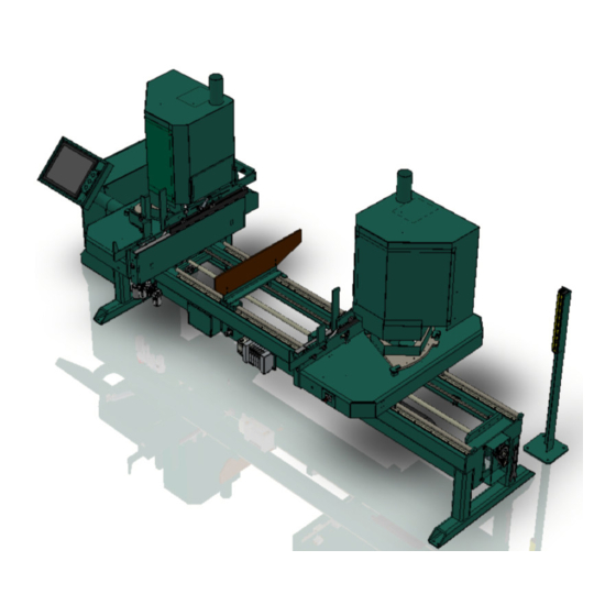
Overview of the 979-2 The Kval Model 979-2 Miter Trim Saw is designed to cut door stops and casing materials up to 26 pieces per minute. Similar to a portable powered miter saw, the blades of the 979-2 cut from above the work pieces through the material face to achieve the best quality possible with all types of moulding materials, including pre-finished casing. - Page 10 Introduction 979-2...
-
Page 11: Safety First
Failure to do so can result in damage to equipment and/or seri- ous injury to personnel. Safety Guidelines In addition to the caution and warning labels affixed to the 979-2 system, follow the guidelines below to help ensure the safety of equipment and personnel. Guideline... -
Page 12: Lock Out Procedure
This policy is required by OSHA regulation 1910.147 and Cal OSHA’S SB198 ruling of July 1991. Use the following lockout procedure to secure the 979-2 while it is powered down. During a lockout, you disconnect all power and shut off the air supply. Be sure to use the tagout guidelines noted below. -
Page 13: Lockout And Tagout Guidelines
R ..Recognize energy type (electrical, pneumatic, mechanical, etc.) O..OFF! Shut off all power sources and isolating devices P..Place lock and tag E..ENERGY: Release stored energy to a zero-energy state R ..Recheck controls and test to insure they are in the “OFF” state 979-2... -
Page 14: Zero-Energy Start-Up
Provisions which ensure protection during shift changes when contractor or out- side help is used must also comply with the lock-out/tag-out procedures. Comprehensive lock-out/tag- 979-2... - Page 15 Proper lock-out/tag-out can save lives, limbs, and money. Help make your work environment safe for yourself and your fellow employees. Make sure you follow the P-R-OP-E-R lock-out/tag-out proce- dures, and that those around you do also. YOUR LIFE MAY DEPEND ON IT. 979-2...
-
Page 16: 979-2 Guard Placements And Purpose
Kerf Blade Guard (for optional Kerf Saw): Mounted directly over the kerf blade(s) on both kerf routers located on either end of the 979-2. The kerf blade guard is designed to protect the operator from the kerf blade, whether or not the machine is operating. -
Page 17: Initial Set Up
Initial Set up Initial Set up Your new Kval machine arrives at your plant crated, banded, taped, with painted set collars on all shafts, keeping all of the precision moving parts secure during shipping. To protect against damaging the machine with the forklift, move the machine as close as possible to the area where it will be stationed before removing it from the crate Use caution when removing the machine from the crate. -
Page 18: Trubolt Wedge Anchor
INSTALLATION INSTRUCTIONS Drill a ½-inch hole, minimum of 6-inch depth. Clean hole. NOTE: Kval recommends drilling completely through the slab. If in the future the machine needs to be moved, remove the Red Head nut and pound the bolt flush with the floor surface. -
Page 19: Electrical Connections Overview
NOTE: The main electrical panel contains the PLC. The 979-2 requires three phase power. Refer to the plant layout diagram or the brass information plate to determine the voltage required. If the 979-2 is equipped with kerf saws, an additional 120-volt source is required. - Page 20 979-2...
-
Page 21: Chapter 2 Operation
Operation CHAPTER 2 The following chapters explain normal operation of the 979-2. 979-2... - Page 22 Operation 979-2...
-
Page 23: Machine Tour
Machine Tour Machine Tour Left or Fixed Head Right or Movable Head Control Transformer Button Start Machine Button E-Stop Button E-Stop Pull Cord (Optional) E-Stop Button 979-2... - Page 24 979-2...
-
Page 25: Quick Start
Quick Start Quick Start Power up the 979-2. See “Powering Up the 979-2” on page 19. Select a mode. See “Modes” on page 21. Pick one Select a preset - See “Presets” on page 24. or manually enter a length - See “Manual Length Entry” on page 27.t... - Page 26 979-2...
-
Page 27: Turning The 979-2 On And Off
Turning the 979-2 On and Off Turning the 979-2 On and Off Use the procedures below for powering up and powering down the 979-2. Powering Up the 979-2 Powering up the system includes: • Applying power to the entire system •... -
Page 28: To Power Down The 979-2
Push in the CONTROL TRANSFORMER switch. This kills power to the machine. All status lights should be off. Kval also recommends that you turn the disconnect switches on both electrical cabinets to OFF; this helps reduce possible damage resulting from power surges from electrical storms. -
Page 29: Modes
• Head: Puts the Left Head at 45º and the Right Head at 45º • Right: Puts the Left Head at 45º and the Right Head at 0º. • Stop: Puts the Left Head at 0º and the Right Head at 0º 979-2... -
Page 30: Mechanical Set-Up
NOTE: Wide jamb mode has better clamping ability than nar- row jamb mode; tighter clamping produces cleaner saw cuts. Wide jamb mode can be used on narrow stock. The disadvantage is that wide jamb mode is slower by about 3 boards per minute. 979-2... - Page 31 End stop distance indicator.Set to Front hopper adjustment bolts stock width distance. Adjust front hopper stop height to clear stock by app. 1/8” Rear Hopper Stop Adjust rear hopper stop to set hopper width to 1/8” wider than stock. 979-2...
-
Page 32: Presets
Note: For Right Jamb and Left Jamb modes there are 12 quick access presets available. For Head and Stop modes there are 24 quick access presets available. To access presets 13 to 24 in Head and Stop modes, press Next Page. Note: See “Preset Screen” on page 31. for a detailed description of this screen. 979-2... -
Page 33: Direct Access Preset Selection
The “O.K. to Move” popup will appear. Hold the O.K. to move button until the head is in position. The 979 is now ready for work. Note: See “Length / Preset Screens” on page 32. for a detailed description of this screen. 979-2... -
Page 34: Preset Storage
Press Previous Menu until you reach the Main Run Screen. On the Main Run screen press Refresh Text to make the new presets visible. Turn the Set Up key switch to Off. Note: See “Length Only Screen” on page 34. for a detailed description of this screen. 979-2... -
Page 35: Manual Length Entry
The “O.K. to Move” popup will appear. Hold the O.K. to move button until the head is in position. The 979 is now ready for work. Note: See “Length / Preset Screens” on page 32. for a detailed description of this screen. 979-2... - Page 36 979-2...
-
Page 37: Touch Screen Interface
This safety feature ensures the operator will be in a safe position at the touchscreen and not near the moving heads. If “Abort Move” is pressed the dis- play returns to the previous screen. 979-2... -
Page 38: Run Screen
Updates the text for the current display. Machine Data Moves to the Machine Data screen. See “Machine Data” on page 35. Clamp Setup Turns off the saws to allow the user to safely set up the clamps. page 22\ 979-2... -
Page 39: Preset Screen
Displays the quantity saved in the currently selected preset. Present Length (Fractional Displays the length saved in the currently selected preset in decimal format Present Length (Decimal) Displays the length saved in the currently selected preset in fractional format. 979-2... -
Page 40: Length / Preset Screens
Used to call the Key Fractional screen (page 33) for entering numerical data in a frac- tional format. Decimal Used to enter a decimal point into a keypad entered numeric value. Keypad Used to enter a numeric value. Keypad Display Displays keypad entered digits. 979-2... -
Page 41: Keypad Fractional Screen
When the correct value has been entered press previous menu to return to the previous screen. Keypad Quantity Screen Keypad This screen is used to change the number of parts to be processed. Enter the desired number using the keypad then press Close Menu to return to the previous screen. 979-2... -
Page 42: Length Only Screen
Used to call the Key Fractional screen (page 33) for entering a length in fractional for- mat. Decimal Used to enter a decimal point into a keypad entered length. Keypad Used to enter a length. Keypad Display Displays the length entered from the keypad. 979-2... -
Page 43: Machine Data
Machine Total Total number of boards run through the machine. Daily Total Number of boards run throught the machine since Reset Daily was pressed. Reset Daily Sets the Daily Total to 0. Previous Menu Returns to the previously displayed menu. 979-2... -
Page 44: Clamp Setup
Pressing the Clamp Setup button on either the Run screen (“Run Screen” on page 30) or the Preset screen (“Preset Screen” on page 31) turns off the saws to allow for safe clamp set up (see “Mechanical Set-up” on page 22). After the clamps are set use the screens shown above to re-start the saws. 979-2... -
Page 45: Chapter 3 Calibration
Calibration”; if the new value is incorrect go back to step 10. NOTE: To reduce waste, use the same board used in step 4. Simply modify the cut length to app. 2 inches shorter. Press “Close Menu”. Make confirmation cut by going back to step 3. 979-2... - Page 46 NOTE: To reduce waste, use the same board used in step 4. Simply modify the cut length to app. 2 inches shorter. A note on calibration: A 979-2 properly calibrated and mechanically set up will accurately make cuts within 1/1000” tolerance. Cut length accuracy is more dependant on material quality than the 979-2.
-
Page 47: Chapter 4 Maintenance
Maintenance CHAPTER 4 This chapter describes how to maintain the 979-2 system. This chapter contains the following informa- tion: • Maintenance schedule.......page 40 • Lubrication requirements....page 42 979-2... -
Page 48: Maintenance Schedule
Fastening Nuts • Check the air pressure to make sure it is set at 100 psi. • Refill lubricator with an ISO 32 standard hydraulic oil (use KVAL part# SYSLUBEG). Weekly • Check the machine for smooth motion through a complete door cycle. -
Page 49: May And December Checkups
• Grease all bearings and tighten all bolts (see grease locations on illustrations,). Access to some grease fittings is difficult and will require a special needle point grease tip (supplied with your system). • Clean and lubricate all slides and cylinder rods with dry silicone spray. • Tighten all bolts. 979-2... -
Page 50: Lubrication Requirements
Use Dura-Lith grease: 1 gram every 60 days. Approved Lubrication Products for Lubricators Chevron AW Hydraulic Oil 32 – or KVAL P/N SYSLUBG or G-C lubricants light AW R&O or Mobile DTE 24 or Shell Tellus32 or Gulf Harmony 32. Gear Motor Lubrication Requirements Oil change is recommended after 2000 hours or six months of operation. -
Page 51: Adjusting The Air Line Lubricator (Not Available On All Machines)
Check the lines every week to two weeks. Sight Glass. Check rate: 1 drop for ever Set top valve to 100psi two door cycles. Adjustment Knob Filter Regulator Lubricator Set bottom valve to 90 psi NOTE: The Lubricator is not installed on all machines. 979-2... -
Page 52: Grease Points
Maintenance Grease Points Main Frame Bottom View Bottom View 979-2... -
Page 53: Fixed Head
Lubrication Requirements Fixed Head 979-2... -
Page 54: Movable Head
Maintenance Movable Head Bottom View 979-2... -
Page 55: Cut Depth Set-Up
First” section of this manual for further information on lock and tag-out procedures. The 979-2 saw travel is controlled at two points within the saw carriage: the mounting plate and the limit switch. To adjust the saw's travel you will have to adjust both. - Page 56 979-2...
- Page 57 Cut Depth Set-up 979-2...
- Page 58 979-2...
- Page 59 Cut Depth Set-up 979-2...
- Page 60 979-2...
-
Page 61: Feed Cylinder Replacement And Feed Dog Adjustment Procedure
Feed Dog Plate Feed Cylinder Feed Reverse Stop Stop Replace the Feed Cylinder Feed Cylinder. Adjust the new Feed Cylinder placement to insure Feed Dog Plate has smooth travel for the full range of motion. Tighten the Feed Cylinder lock nuts. 979-2... - Page 62 Movable Head Forward Feed Stop Fixed Head Forward Feed Stop Fixed Head Dog Plate Movable Head Dog Plate Fixed Head Alignment Mark Fixed Head Fixed Head T Square Movable Head Movable Head Middle Feed Dog Plate Plate Feed Middle Dog 979-2...
- Page 63 Adjust the Feed Reverse stop for a gap of 8 15/16” between the forward edge of both Feed Dog Plates and the Feed Forward Stop. 8 15/16” Feed Forward Feed Dog Plate Feed Reverse Stop Stop Reinstall the inside covers. 979-2...
- Page 64 979-2...
-
Page 65: Chapter 5 Troubleshooting
Troubleshooting CHAPTER 5 979-2... -
Page 66: Troubleshooting The Air Cylinders
If the valve is not receiving an electrical signal, for instructions. It might be necessary to call in a specialist or check with KVAL customer service at 1-800-553-5825. If an Air Leak is coming from an exhaust port on the solenoid air bank:... -
Page 67: Adjusting Cylinder Extension Speed
When the air leak stops or weakens it usually means that one or more of the cylinders that the solenoid is operating are faulty. Adjusting Cylinder Extension Speed: Adjusting Cylinder Retraction Speed: 979-2... -
Page 68: Troubleshooting Electrical Problems
For more information on the limit switch specifications, see the manu- facturer’s information. For limit switch adjustment procedures, refer to. If a solenoid valve is suspected, and not cleared in the air checks section (see), it can be electrically jumped to check operation. 979-2... -
Page 69: Troubleshooting With The Status Light Panel
If one RELAY or more lights are OFF, follow the process below to ascertain the cause. E-STOP 24VDC NOTE: Be sure to proceed down the table, starting with the CONTROL POWER light. 979-2... - Page 70 • Check for 110 VAC between #2 and #3B. If there is 110 VAC, go to next step: If the contact on the Rear Access Gate is closed and there is no power between #2 and #3B, check for wiring problems. 979-2...
- Page 71 24VDC Home the Check between DC+ and DC- for 24VDC. If no DC voltage, disconnect the 979-2 + Brown/Red and - Blue/Black wires from the 24VDC power supply and (see) check for DC voltage where those wires were disconnected.
-
Page 72: Adjusting Limit Switches
If the arm is moved to the full extent of its travel and you do not hear the limit switch “click”, the switch needs to be adjusted. Use the set screw on the limit switch arm and adjust the arm to activate at the desired degree of rotation (see illustrations below). Examples of Limit Switches: 979-2... -
Page 73: Troubleshooting Photo Detectors
24VDC to PLC. If no object is sensed the Photo Eye sends a 0VDC to the PLC. If the photo detector is dirty, it will falsely sense the presence of a door, or other obstruction, and stop the machine operation. If a suspected Photo Detector is clean check for the proper DC Voltage. 979-2... -
Page 74: Getting Help From Kval
Technical Support business hours are 4:00 AM to 4:30 PM Pacific Standard Time, Monday through Fri- day. Product Return Procedure If you’ve contacted Kval for help and it is determined that a return is necessary, use the procedure below to return the machine or part. Note: Non-Warranty returns are subject to a 15% restocking charge. -
Page 75: Touch Screen Troubleshooting
See page 77 MACHINE PREVIOUS CALIBRATION SENORS MENU See page 37 See page 68 See page 85 For information of each of the screens listed in the Maintenance menu refers to the page listed between the arrows: See page __ 979-2... -
Page 76: Machine Status
Limit switch: See “Heads - Bottom View” on page 88. for location. Retracted I-10 Limit switch: See “Heads - Bottom View” on page 88. for location. Extended I-11 Limit switch: See “Heads - Bottom View” on page 88. for location. 979-2... -
Page 77: Sequence Does Not Complete
Limit switch: See “Right or Movable Head” on page 86. for location. LS Feed retracted (I-10) Limit switch: See “Heads - Bottom View” on page 88. for location. Saw Motors Retracted (M-20) Internal PLC register, requires PC to PLC interface and WindLDR program. 979-2... -
Page 78: Start Sequence (Feed)
Photo Eye: See “Left or Fixed Head” on page 87. for location. PE Board Straight #2 (I-13) Photo Eye: See “Right or Movable Head” on page 86. for location. Straight (T-11) Internal PLC timer, requires PC to PLC interface and WindLDR program. 979-2... -
Page 79: Saws Do Not Extend
Internal PLC register, requires PC to PLC interface and WindLDR program. Left Cut Started (M-34) Internal PLC register, requires PC to PLC interface and WindLDR program. Right Cut Started (M-36) Internal PLC register, requires PC to PLC interface and WindLDR program. 979-2... -
Page 80: Saws Do Not Start
Underneath left head at retracted end of Kerf saw travel, no picture available. Right Kerf Retracted (I-15) Underneath right head at retracted end of Kerf saw travel, no picture available. Setup Mode (M-290) Internal PLC register, requires PC to PLC interface and WindLDR program. 979-2... -
Page 81: Heads Do Not Adjust
Underneath left head at retracted end of Kerf saw travel, no picture available. Right Kerf Retracted (I-15) Underneath right head at retracted end of Kerf saw travel, no picture available. OK to Move Heads (M-290) Internal PLC register, requires PC to PLC interface and WindLDR program. 979-2... -
Page 82: Plc Input-Bit Status
Limit switch: See “Heads - Bottom View” on page 88. for location. I-03 ## Not used I-04 Start Sequence Foot Switch, no picture available. I-05 ## Not used I06 Left Saw UP Limit switch: See “Left or Fixed Head” on page 87. for location. 979-2... -
Page 83: Plc Output-Bit Status
Blow off for photo eyes on both left and right heads. See page 87 and page 86. Q-05 Clamp Clamps on both left and right heads. No picture available. Q-6 Feed Cylinder Cylinder to power feed an both left and right heads. No picture available. 979-2... -
Page 84: Plc M-Bit Status
PLC M-Bit Status All M-Bits are internal PLC registers. Viewing requires PC to PLC interface and WindLDR program. 979-2... -
Page 85: Galil Io Status
GALIL OUT #3 (0 - 0) PLC:I-43,GALIL:0-04 GALIL OUT #4 (45 - 0) PLC:I-44,GALIL:0-05 GALIL OUT #5 (0 - 45) PLC:I-45,GALIL:0-06 GALIL OUT #6 (In Position) PLC:I-46,GALIL:0-07 GALIL OUT #7 (Quant = 0 & In Position) PLC:I-47,GALIL:0-08 GALIL OUT #8 (Homed) 979-2... -
Page 86: Kerf Saw Sequence (Optional)
Motor Start Q-01 Right Kerf saw motor located under left head. No picture available. Cylinder Down Q-010 Cylinder to move right Kerf saw. No picture available. Saw Motors Retracted (M-20) Internal PLC register, requires PC to PLC interface and WindLDR program. 979-2... -
Page 87: Technical Support
Touch Screen Troubleshooting Technical Support Contact information. 979-2... -
Page 88: Servo Trouble Shooting
Limit - Switch Timing See page 83 See page 81 Both the “Motor & Thread” and “I/O & Error Log” buttons call screens that display the present motion control system status. This information may be required by a service technician during troubleshooting. 979-2... -
Page 89: Limit - Switch Timing
Note: The Home Limit Switch and /or Limit Switch Activator Bolt is painted orange on some models. General process description: Note: Most KVAL machines automate this process, see “979-2 X Axis Limit Switch Timing” on page 82 for machine specific instructions. -
Page 90: 979-2 X Axis Limit Switch Timing
979-2 X Axis Limit Switch Timing From the main run screen press Servo Troubleshooting. Press Limit Switch Timing. The O.K> to move screen will appear. Press the O.K to move button to allow the machine to run the limit switch timing routine.The movable head will travel away from... -
Page 91: Set Minimum Cut
Set Mini- mum Cut routine.The movable head will travel toward the fixed head and stop. The minimum cut distances will appear at the top of the servo trouble shooting screen. 979-2... - Page 92 979-2...
-
Page 93: Part Locations
Part Locations Part Locations General Top View Left or Fixed Head Right or Movable Head Control Transformer Button Start Machine Button E-Stop Button E-Stop Button 979-2... -
Page 94: Right Or Movable Head
Control Circuit #3 *Retracting the Right Saw Extend cylinder will cause the Right Saw to drop. Extending this cylinder will cause the Right Saw to rise. Machine Sensor locations Touch Screen Description PLC Output label Touch Screen Label (PLC port) 979-2... -
Page 95: Left Or Fixed Head
SV-34 (Q34) *Retracting the Left Saw Extend cylinder will cause the Left Saw to drop. Extending this cylinder will cause the Left Saw to rise. Description PLC Output label Machine Sensor locations Touch Screen Touch Screen Label (PLC port) 979-2... -
Page 96: Heads - Bottom View
Feed Forward Limit Switch Left Saw 45º Machine Sensor locations Touch Screen Left Head Bottom View Cylinder: Left Saw 45º Extend Q32 Retract Q33 Limit Switch Left Saw 45º Description PLC Output label Right Head Touch Screen Label (PLC port) 979-2... -
Page 97: Top View And Main Valve Bank
Limit Switch +Crash LS-50 (I50) Machine Sensor locations Touch Screen Main Valve Bank Port B Port B Left Saw 0º Right Saw 0º Feed Cylinder & counter Clamp Blow Off Port A Port A Left Saw 45º Right Saw 45º 979-2... - Page 98 979-2...
-
Page 99: Warranty
Warranty Warranty KVAL Inc. will repair or replace any unserviceable parts not covered by their own manufacturer's war- ranty when malfunction is caused by faulty manufacturing or design up to one year or 2080 production hours after the delivery date, whichever comes first. This warranty does not cover items that wear out during normal use, such as (but not limited to) tooling, chipout blocks, and screwdriver bits. - Page 100 979-2...
- Page 101 4 troubleshooting 60 product return procedure 66 proximity sensors See photo detectors return material authorization (RMA) 66 returning the product to Kval 66 safety cage guidelines for entering 3 safety guidelines 3 sensors See photo detectors shutoff valve, air 43...
- Page 102 979-2...
Need help?
Do you have a question about the 979-2 and is the answer not in the manual?
Questions and answers