Table of Contents
Advertisement
Quick Links
Advertisement
Table of Contents

Subscribe to Our Youtube Channel
Related Manuals for Neousys Technology POC-400 Series


Summary of Contents for Neousys Technology POC-400 Series
- Page 1 Neousys Technology Inc. POC-400 Series User Manual Revision 1.0...
-
Page 2: Table Of Contents
2.2.5 DisplayPort......................25 2.2.6 IEEE 802.3at Power over Ethernet Port (POC-400 only) ........26 2.2.7 3-Pin Terminal Block ..................27 POC-400 Series COM Port Panel ................28 2.3.1 Power Button ....................29 2.3.2 Reset Button ..................... 29 2.3.3 COM Port (COM1) .................... 30 2.3.4... - Page 3 Table of Contents 3.5.1 Standard Wall Mount (Optional Accessory) ............57 3.5.2 Vertical Wall Mount (Optional Accessory) ............58 Powering On the System ..................59 3.6.1 Powering On Using the Power Button ............... 59 3.6.2 Powering On Using An External Non-Latched Switch ........60 3.6.3 Powering On Using Wake-on-LAN ..............
- Page 4 Table of Contents GetStatusPoEPort ........................97 EnablePoEPort........................98 DisablePoEPort ........................99...
-
Page 5: Legal Information
For questions in regards to hardware/ software compatibility, customers should contact Neousys Technology Inc. sales representative or technical support. To the extent permitted by applicable laws, Neousys Technology Inc. shall NOT be responsible for any interoperability or compatibility issues that may arise when (1) products, software, or options not certified and supported;... -
Page 6: Contact Information
Neousys Technology Inc. (Taipei, Taiwan) 15F, No.868-3, Zhongzheng Rd., Zhonghe Dist., New Taipei City, 23586, Taiwan Tel: +886-2-2223-6182 Fax: +886-2-2223-6183 Email, Website Americas Neousys Technology America Inc. 3384 Commercial Avenue, Northbrook, IL 60062, USA (Illinois, USA) Tel: +1-847-656-3298 Email, Website China Neousys Technology (China) Ltd. -
Page 7: Copyright Notice
This manual is intended to be used as an informative guide only and is subject to change without prior notice. It does not represent commitment from Neousys Technology Inc. Neousys Technology Inc. shall not be liable for any direct, indirect, special, incidental, or consequential damages arising from the use of the product or documentation, nor for any infringement on third party rights. -
Page 8: Safety Precautions
Safety Precautions Safety Precautions ⚫ Read these instructions carefully before you install, operate, or transport the system. ⚫ Install the system or DIN rail associated with, at a sturdy location ⚫ Install the power socket outlet near the system where it is easily accessible ⚫... -
Page 9: Service And Maintenance
Service and Maintenance/ ESD Precautions Service and Maintenance ⚫ ONLY qualified personnel should service the system ⚫ Shutdown the system, disconnect the power cord and all other connections before servicing the system ⚫ When replacing/ installing additional components (expansion card, memory module, etc.), insert them as gently as possible while assuring proper connector engagement ESD Precautions... -
Page 10: About This Manual
About This Manual About This Manual This manual introduces and demonstrates installation procedures of Neousys POC-400 series systems. Revision History Version Date Description Jul. 2022 Initial release... -
Page 11: Introduction
POC-400 Series Introduction Neousys Technology POC-400 is an ultra-compact fanless embedded computer for industrial applications. It utilizes the latest Intel ® Elkhart Lake platform Atom ® x6425E 4-core CPU that can deliver 1.8x and 2x the performance improvement for the CPU and GPU respectively, compared to the previous generation. -
Page 12: Specification Of Poc-400
POC-400 Series Specification of POC-400 System Core Intel ® Elkhart Lake Atom ® x6425E quad-core 2.0GHz/3.0GHz 12W Processor processor ® Graphics Integrated Intel UHD Graphics Memory Up to 32 GB DDR4-3200 SDRAM by one SODIMM socket Panel I/O Interface ®... - Page 13 CE/FCC Class A, according to EN 55032 & EN 55035 * The 100% CPU/GPU loading for high temperature test is applied using Passmark® BurnInTest™ v8.0. For detail testing criteria, please contact Neousys Technology ** For sub-zero operating temperature, a wide temperature HDD drive or Solid State Disk...
-
Page 14: Specification Of Poc-410
POC-400 Series Specification of POC-410 System Core ® ® Intel Elkhart Lake Atom x6425E quad-core 2.0GHz/3.0GHz 12W Processor processor ® Graphics Integrated Intel UHD Graphics Memory Up to 32 GB DDR4-3200 SDRAM by one SODIMM socket Panel I/O Interface ®... - Page 15 CE/FCC Class A, according to EN 55032 & EN 55035 * The 100% CPU/GPU loading for high temperature test is applied using Passmark® BurnInTest™ v8.0. For detail testing criteria, please contact Neousys Technology ** For sub-zero operating temperature, a wide temperature HDD drive or Solid State Disk...
-
Page 16: Dimension
POC-400 Series Dimension 1.3.1 Superior View 1.3.2 Front Panel View... -
Page 17: Bottom View
POC-400 Series 1.3.3 Bottom View... -
Page 18: Poc-400 Series Mounting Options
POC-400 Series POC-400 Series Mounting Options The system comes with various mounting options such as DIN-rail and wall-mount bracket. DIN-rail mount clip is shipped with POC-400 series as standard mounting option. 1.4.1 DIN-Rail Mount Clip... -
Page 19: System Overview
POC-400 Series System Overview Upon receiving and unpacking your POC-400 series, please check immediately if the package contains all the items listed in the following table. If any item(s) are missing or damaged, please contact your local dealer or Neousys Technology. -
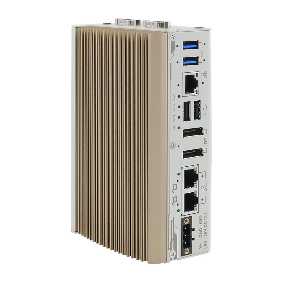
Page 20: Poc-400 Series Front Panel
POC-400 Series POC-400 Series Front Panel The front panel of POC-400 systems feature rich I/O ports, it has three 2.5G Ethernet ports (two are PoE+ ports for POC-400), two USB3.1 Gen1 ports, two USB2.0 ports, two DisplayPort ports for video output and 3-pin terminal block for DC input. -
Page 21: Usb 3.1 Gen 1 Port
UEFI USB support is also provided so you can use USB keyboard/mouse in UEFI shell environment xHCI driver is supported natively in Windows 10, therefore you do not need to install xHCI driver in prior to utilize USB function on POC-400 series. -
Page 22: G Ethernet Port
POC-400 Series 2.2.2 2.5G Ethernet Port The system offers three 2.5Gb Ethernet ports using Intel® I225 GbE controller. From top to bottom, they are port #1, #2 and #3. When plugged in and connected via the Ethernet cable, the LEDs on the RJ45 connector indicate connection status and speed. -
Page 23: System Status Led
POC-400 Series 2.2.3 System Status LED There are four LED indicators on the front panel: PWR, HDD, WDT and IGN. The descriptions of these four LEDs are listed in the following table. Indicator Color Description Green Power indicator, lid when system is on... -
Page 24: Usb 2.0 Port
POC-400 Series 2.2.4 USB 2.0 Port The USB2.0 ports are implemented via native xHCI (eXtensible Host Controller Interface) and are backward compatible with USB 1.1 and USB 1.0 devices. UEFI USB support is also provided so you can use USB keyboard/ mouse in UEFI shell environment. -
Page 25: Displayport
POC-400 Series 2.2.5 DisplayPort The system has two DisplayPort (DP) outputs which are digital display interfaces that mainly connect video source and carry audio to a display device. When connecting a DP, it can deliver up to 4K UHD (4096 x 2160 @ 60Hz) in resolution. The system is designed to support passive DP adapter/ cable. -
Page 26: Ieee 802.3At Power Over Ethernet Port (Poc-400 Only)
POC-400 Series 2.2.6 IEEE 802.3at Power over Ethernet Port (POC-400 only) The Gigabit Power over Ethernet (PoE) port supply both power and data on a standard CAT-5/ CAT-6 Ethernet cable. Acting as a PSE (Power Sourcing Equipment), compliant with IEEE 802.3at, each port delivers up to 25W to a Powered Device (PD). -
Page 27: 3-Pin Terminal Block
POC-400 Series 2.2.7 3-Pin Terminal Block The system accepts a wide range of DC power input from 8 to 35V via a 3-pin pluggable terminal block, which is fit for field usage where DC power is usually provided. The screw clamping mechanism on the terminal block offers connection reliability when wiring DC power. -
Page 28: Poc-400 Series Com Port Panel
POC-400 Series POC-400 Series COM Port Panel The COM port panel of POC-400 series features additional I/O functions, such as a 3.5mm speaker-out/ microphone-in jack, COM ports and antenna holes for antenna installation. Item Description Power button Use this button to turn on or shutdown the system. -
Page 29: Power Button
POC-400 Series 2.3.1 Power Button The power button is a non-latched switch for ATX mode on/off operation. Press to turn on the system, PWR LED should light up and to turn off, you can either issue a shutdown command in the OS, or just press the power button. In case of system halts, you can press and hold the power button for 5 seconds to force-shutdown the system. -
Page 30: Com Port (Com1)
POC-400 Series 2.3.3 COM Port (COM1) Implemented using industrial-grade ITE8786 Super IO chip (-40 to 85°C) and provide up to 921600 bps baud rate, COM1 is a software-configurable RS-232/422/485 port via 9-pin D-Sub male connector. The operation mode, slew rate and termination of COM1 can be set in BIOS setup utility. -
Page 31: Com Ports (Com2/ Com3/ Com4)
POC-400 Series 2.3.4 COM Ports (COM2/ COM3/ COM4) Implemented using industrial-grade ITE8786 Super IO chip (-40 to 85°C) and provide up to 921600 bps baud rate, the second D-Sub male connector (COM2/ 3/ 4) can be configured in BIOS as single RS-422/ 485 port (COM2) or three 3-wire RS-232 ports (COM2/COM3/COM4). -
Page 32: Mm Microphone-In/ Speaker-Out Jack
POC-400 Series 2.3.5 3.5mm Microphone-in/ Speaker-out Jack There is a single 3.5mm audio jack on the top panel. The port is used for microphone input as well as speaker output. To utilize the audio function in Windows, you need to install corresponding drivers. -
Page 33: Poc-400 Series Internal I/O
POC-400 Series POC-400 Series Internal I/O The system’s internal I/O connectors consist of a SO-DIMM socket, M.2 2280 M key SATA interface port, M.2 E key port and a MezIO port for application-oriented expansion purposes. 2.4.1 SO-DIMM Memory Socket The system has an internal SO-DIMM slot supporting a single DDR4-3200 memory... -
Page 34: M.2 2230 E Key Socket
POC-400 Series 2.4.2 M.2 2230 E Key Socket The system has an M.2 2230 E key socket that offers PCIe Gen3 x1 and USB2.0 signal for WiFi module installation. For SMA antenna installation, there are four dedicated openings located on both sides of the chassis. - Page 35 POC-400 Series M.2 2230 E Key Pin Definition Pin # Signal Pin # Signal +3V3 USB_D+ +3V3 USB_D- Mechanical Key PETP0 PETN0 PER P0 PER N0 REFCLK_P0 REFCLK_N0 CLKREQ# PERST# W_DISABLE# +3V3 +3V3...
-
Page 36: 2280 M Key
POC-400 Series 2.4.3 M.2 2280 M Key The system has an M.2 2280 slot (SATA signal only) for you to install an M.2 SATA SSD for faster access over traditional hard disk drives. NOTE The M.2 slot is only compatible with SATA signal M.2 SSD only. - Page 37 POC-400 Series M.2 2280 M Key Pin Definition Pin # Signal Pin # Signal +3V3 +3V3 DAS/DSS_N +3V3 +3V3 +3V3 +3V3 DEVSLP SATA-B+ SATA-B- SATA-A- SATA-A+ PERST N Mechanical Key SUSCLK PEDET +3V3 +3V3 +3V3...
-
Page 38: Mezio Tm Interface
3-point mounted mezzanine structure. A MezIO module can leverage these signals to implement comprehensive I/O functions. POC-400 series incorporates MezIO interface and universal mechanical design to accommodate Neousys’ standard MezIO modules. For customers who want to... -
Page 39: Mezio Interface Pin Definition
POC-400 Series 2.5.1 MezIO Interface Pin Definition MezIO interface leverages FCI BERGSTAK® board-to-board connector to provide interconnectivity of high-speed signals. The receptacle part on the PCBA is FCI 61082-063402LF while the plug part on the MezIO module is FCI 61083-064402LF. -
Page 40: Mezio Modules For Poc-400 Series
POC-400 Series 2.5.2 MezIO Modules for POC-400 Series Neousys offers MezIO modules to expand I/O functions for Neousys systems. With the addition of a MezIO module into your system, it offers extra RS-232/ 422/ 485 ports, isolated digital I/ O, 2.5” HDD/ SSD accommodation, USB or ignition power control. -
Page 41: System Installation
POC-400 Series System Installation Before disassembling the system enclosure and installing components and modules, please make sure you have done the following: ⚫ It is recommended that only qualified service personnel should install and service this product to avoid injury or damage to the system. -
Page 42: Disassembling The System Enclosure
POC-400 Series Disassembling the System Enclosure To install necessary components such as memory module, M.2 modules or MezIO module, you need to disassemble the POC-400 system enclosure: To disassemble POC-400, unfasten the screws shown in the following illustrations. Front panel Rear panel Unfasten the screws at the bottom of the enclosure. - Page 43 POC-400 Series Gently slide the enclosure open. Remove the SO-DIMM module heatsink by unscrewing the screws indicated to gain access to internal expansion slots.
-
Page 44: Installing Internal Components
Installing Internal Components 3.2.1 SO-DIMM Installation There is one SO-DIMM memory slot on POC-400 series motherboard. Please follow the procedures below to install the memory module. Disassemble the system enclosure 2. The SO-DIMM slot can be located once the enclosure and heatsink have been removed. - Page 45 POC-400 Series 4. Remove the memory thermal pad cover and secure the heatsink with the screws indicated. Remove memory thermal pad cover Secure the heatsink Reinstall the system enclosure.
-
Page 46: 2280 M Key Module Installation
POC-400 Series 3.2.2 M.2 2280 M Key Module Installation There is an M.2 2280 M key module expansion slot on POC-400 series motherboard. Please follow the procedures below for installation. Disassemble the system enclosure. 2. The M.2 2280 M key expansion can be located once the enclosure has been removed. - Page 47 POC-400 Series 4. Gently press the card down and secure with a screw. Reinstall the system enclosure.
-
Page 48: 2230 E Key Module Installation
POC-400 Series 3.2.3 M.2 2230 E Key Module Installation There is an M.2 E key expansion slot on POC-400 series motherboard for WiFi, Google TPU or Movidius VPU module installation. Please follow the procedures below for installation. Disassemble the system enclosure. - Page 49 POC-400 Series 4. If you are installing a WiFi module, you will need to install the module’s antennae (please refer to the module’s user manual on antennae cable connection). 5. Remove the M.2 E key thermal pad cover and secure the heatsink with the screws indicated.
- Page 50 POC-400 Series 7. Please refer to the illustration below to secure the SMA antenna. Secure antenna body on enclosure Install the external antenna Reinstall the system enclosure and attach the external antennae to complete the installation.
-
Page 51: Mezio Tm Module Installation
POC-400 Series 3.2.4 MezIO Module Installation The system comes with a MezIO module expansion slot. For specific MezIO module I/ O functionalities, please refer to the MezIO Module section. For installation, please refer to the following procedure. Disassemble the system enclosure. - Page 52 POC-400 Series 4. To install, match the three (3) screw holes to the standoffs and the MezIO port, gently lower the module onto the PCBA. The MezIO port should engage if the three (3) standoffs and screw holes meet. Then using the three (3) screws supplied, secure the module by fastening a screw on each standoff.
-
Page 53: Installing The System Enclosure
POC-400 Series Installing the System Enclosure To reinstall the system enclosure, gently slide the L-shaped enclosure back in place making sure the screw hole on the hinge sits on the inside. Place enclosure back in-place Make sure hinge sits on the inside Complete installing the system enclosure by fastening the screws indicated below. - Page 54 POC-400 Series Bottom of the enclosure...
-
Page 55: Din Rail Installation
POC-400 Series DIN Rail Installation The DIN rail is easy to install and it is a convenient way to position the system. The DIN rail has been proven to be most beneficial in the industrial environment where space is limited. The mount plate comes with two M4 screws. Please refer to the illustrations below to install the DIN clip/ rail. - Page 56 POC-400 Series To install the mount plate onto the DIN rail, you must come over the top of the DIN rail, tilting downwards, overlap the top clip edge of the mount plate onto the DIN rail first, then firmly press the bottom-front of the enclosure to clip the bottom edge of the mount plate.
-
Page 57: Wall Mount Installation (Optional Accessory)
POC-400 Series Wall Mount Installation (Optional Accessory) 3.5.1 Standard Wall Mount (Optional Accessory) The optional wall mount bracket allows the system to be mounted horizontally. Please refer to the following installation procedure to install the wall mount. To install, secure the wall mount bracket to the bottom of the system enclosure using the M4 screws provided. -
Page 58: Vertical Wall Mount (Optional Accessory)
POC-400 Series 3.5.2 Vertical Wall Mount (Optional Accessory) To install, secure the wall mount bracket to the rear side panel of the system enclosure using the M4 screws provided. Dimension illustration of the install vertical wall mount bracket for you... -
Page 59: Powering On The System
POC-400 Series Powering On the System There are five methods to power on the system ⚫ Pressing the power button ⚫ Via an external non-latched switch ⚫ Sending a LAN packet via Ethernet (Wake-on-LAN) ⚫ Using the ignition signal input (if MezIO-V20 is installed) We will describe the processes and actions involved for the first four methods in this section and the ignition signal input method will be described in section 3.7. -
Page 60: Powering On Using An External Non-Latched Switch
POC-400 Series 3.6.2 Powering On Using An External Non-Latched Switch For an application which places the system inside a cabinet, it’s useful to control powering on/off the system using an external switch. The system provides an on-board connector for connecting a latched/ non-latched switch and behaving either AT-mode or ATX-mode power on/off control. -
Page 61: Powering On Using Wake-On-Lan
POC-400 Series 3.6.3 Powering On Using Wake-on-LAN Wake-on-LAN (WOL) is a mechanism to wake up a computer system from a S3 (standby), S4 (Hibernate) or S5 (system off with standby power) state via issuing Subnet Directed Broadcasts (SDB) or a magic packet. The system implements the Wake-on-LAN function for the GbE port #1 shown below. - Page 62 POC-400 Series In Windows systems, identify the Local Area Connection of the corresponding Gigabit Controller and click the Configure button. Click the Power Management tag, and check the following two options accordingly...
- Page 63 POC-400 Series ⚫ Wake on Magic Packet The system can wake from S3 or S4 state when receiving a magic packet. The magic packet is a broadcast frame containing anywhere within its payload 6 bytes of all 255 (FF FF FF FF FF FF in hexadecimal), followed by sixteen repetitions of the target computer's 48-bit MAC address.
-
Page 64: Ignition Power Control (For Mezio-V20 Only)
POC-400 Series Ignition Power Control (For MezIO-V20 Only) The ignition power control module for in-vehicle applications is a MCU-based implementation that monitors the ignition signal and reacts to turn on/off the system according to predefined on/off delay. Its built-in algorithm supports other features such as ultra-low power standby, battery-low protection, system hard-off, etc. -
Page 65: Additional Features Of Ignition Power Control
POC-400 Series 3.7.2 Additional Features of Ignition Power Control In addition to the typical timing correlation, the ignition power control module offers additional features to provide additional reliability for in-vehicle applications. ⚫ Low battery detection The ignition power control module continuously monitors the voltage of DC input when the system is operational. -
Page 66: Wiring Ignition Signal
POC-400 Series 3.7.3 Wiring Ignition Signal To have ignition power control for in-vehicle usage, you need to supply IGN signal to the system. The IGN input is located on the 3-pin pluggable terminal block (shared with DC power input). For in-vehicle ignition control wiring, please do the following: Connect car Battery+ line (12V for sedan, 24V for bus/truck) to V+. -
Page 67: Configure Your Windows System
POC-400 Series 3.7.4 Configure your Windows system When applying ignition power control to your system, please make sure you’ve configured your Windows system to initiate a shutdown process when pressing the power button. By default, Windows 7/ 8/ 10 goes to sleep (S3) mode when power button is pressed. -
Page 68: Operation Modes Of Ignition Power Control
POC-400 Series 3.7.5 Operation Modes of Ignition Power Control You can use the rotary switch to configure the operation mode. The system offers 16 (0~15) operation modes with different power-on/power-off delay configurations. The ignition control module is also BIOS-configurable. When rotary switch is set to... - Page 69 POC-400 Series ⚫ Mode 3 ~ Mode 12 Mode 3 ~ Mode 12 have various power-on delay and power-off delay. Each mode supports a hard-off timeout of 10 minutes. Mode Power-on Delay Power-off Delay Hard-off Timeout 10 seconds 10 seconds...
-
Page 70: Bios Settings
POC-400 Series BIOS Settings The system is shipped with factory-default BIOS settings optimized for best performance and compatibility. In this section, we’ll illustrate some BIOS settings you may need to set or change prior to operating system installation. Please always make sure you understand the effect of change before you proceed with any changes. -
Page 71: Com1 Port Configuration
POC-400 Series COM1 Port Configuration The system’s COM1 port supports RS-232 (full-duplex), RS-422 (full-duplex) and RS-485 (half-duplex) mode. You can set the COM1 operating mode via BIOS settings. Another option in BIOS called “Slew Rate” defines how sharp the rising/falling edge is for the output signal of COM1. For long-distance RS-422/485 transmission, you may set the “Slew Rate”... -
Page 72: Com2/ 3/ 4 Port Configuration
POC-400 Series COM2/ 3/ 4 Port Configuration The system’s COM2/ 3/ 4 ports support RS-232 (full-duplex) while COM2 also supports RS-422 (full-duplex) and RS-485 (half-duplex) mode. The operating mode can be configured via the BIOS. Another option in BIOS called “Slew Rate” defines how sharp the rising/falling edge is for the output signal. -
Page 73: C-States
POC-400 Series C-States C-States is a power-saving technique implemented in modern Intel processors. It shuts down the clock signals and power for idle logic units inside the CPU to save the energy consumed. The trade-off, however, is a longer latency for CPU to wake up and be 100% operational. -
Page 74: Power Over Ethernet (Poc-400 Only)
POC-400 Series Power over Ethernet (POC-400 Only) The Power over Ethernet (PoE) functionality is available on ports 1 and 2, and it allows for the transmission of data and power delivery while utilizing a single Cat5 and higher grade Ethernet cable. -
Page 75: Power On After Power Failure
POC-400 Series Power On after Power Failure This option defines the system’s behavior when DC power is supplied. Value Description S0 – Power On System is powered on when DC power is supplied. S5 – Power Off System is kept in off state when DC power is supplied. -
Page 76: Position New Boot Device
POC-400 Series Position New Boot Device The “Add Boot Options” allow you to determine whether a newly added device (eg. USB flash disk) is to boot as the first device to boot or the last in the boot sequence. To set the newly-installed boot device as the first or last boot device: Press F2 when the system boots up to enter the BIOS setup utility. -
Page 77: Watchdog Timer
POC-400 Series Watchdog Timer The watchdog timer secures the boot process by means of a timer. Once the timer expires, a reset command is issued to initiate another booting process. There are two options in BIOS menu, “Automatically after POST” and “Manually after Entering OS”. -
Page 78: Os Support And Driver Installation
OS Support and Driver Installation Operating System Compatibility Due to Intel’s policy, POC-400 series only provide driver support for Windows 10 64-bit. For Linux support, please use Linux kernel versions no later than 5.8. The following list contains the operating systems which have been tested in Neousys Technology Inc. -
Page 79: Driver Installation
POC-400 Series Driver Installation The system comes with a “Drivers & Utilities” DVD that offers “one-click” driver installation process. It automatically detects your Windows operating system and installs all necessary drivers for you system with a single click. 5.2.1 Install Drivers Automatically To install drivers automatically, please refer to the following procedures. -
Page 80: Install Drivers Manually
POC-400 Series 5.2.2 Install Drivers Manually You can also manually install each driver for the system. Please note when installing drivers manually, you need to install the drivers in the following sequence mentioned below. Windows 10 (x64) The recommended driver installation sequence is Chipset driver (x:\Driver_Pool\Chipset_ELK\Win_10_64\SetupChipset.exe) -
Page 81: Driver For Watchdog Timer And Dio
POC-400 Series Driver for Watchdog Timer and DIO Neousys provides a driver package which contains function APIs for WDT function and isolated DIO control function (when MezIO-R12, D230 or D220 is installed). You should install the driver package (WDT_DIO_Setup.exe) in prior to use these functions. -
Page 82: Appendix A Using Wdt & Dio
In this section, we’ll illustrate how to use the function library provided by Neousys to program the WDT functions. Currently, WDT driver library supports Windows 10 x64 and WOW64 platform. For other OS support, please contact Neousys Technology for further information. -
Page 83: Wdt And Dio Library Installation
POC-400 Series WDT and DIO Library Installation To setup WDT & DIO Library, please follow instructions below. 1. Execute WDT_DIO_Setup.2.3.1.exe. and the following dialog appears. 2. Click “Next >” and specify the directory of installing related files. The default directory is C:\Neousys\WDT_DIO. - Page 84 POC-400 Series 3. Once the installation has finished, a dialog will appear to prompt you to reboot the system. The WDT & DIO library will take effect after the system has rebooted. 4. When programming your WDT or DIO program, the related files are located in...
-
Page 85: Wdt Function Reference
POC-400 Series WDT Function Reference InitWDT Syntax BOOL InitWDT(void); Description: Initialize the WDT function. You should always invoke InitWDT() before set or start watchdog timer. Parameter None Return Value TRUE: Successfully initialized FALSE: Failed to initialize Usage BOOL bRet = InitWDT() -
Page 86: Startwdt
POC-400 Series StartWDT Syntax BOOL StartWDT(void); Description Starts WDT countdown. Once started, the WDT LED indicator will begin blinking. If ResetWDT() or StopWDT is not invoked before WDT countdowns to 0, the WDT expires and the system resets. Parameter None... -
Page 87: Using Dio Function (With Mezio-R12 Installed)
POC-400 Series Using DIO Function (With MezIO-R12 Installed) Wiring for DIO The digital input function of System series is implemented using a photo-coupler with an internally series-connected 1kΩ resistor. You need to provide a voltage to specify the logic high/low state. The input voltage for logic high is 5~24V, and the input voltage for logic low is 0~1.5V. -
Page 88: Dio Pin Definition
POC-400 Series DIO Pin Definition Pin# Pin Definition Pin# Pin Definition DI_0 DI_GND DI_1 DI_2 DI_GND DI_3 DO_GND DO_GND DO_0 DO_2 DO_1 DO_3 DO_GND... -
Page 89: Dio Function Reference
POC-400 Series DIO Function Reference InitDIO Syntax BOOL InitDIO(void); Description: Initialize the DIO function. You should always invoke InitDIO() before write/read any DIO port/channel. Parameter None Return Value TRUE: Successfully initialized FALSE: Failed to initialize Usage BOOL bRet = InitWDT() -
Page 90: Dowriteline
POC-400 Series DOWriteLine Syntax void DOWriteLine(BYTE ch, BOOL value); Description: Write a single channel of isolated digital output. BYTE value specifies the DO channel to be written. ch should be a value of 0 ~ 3. Parameter value BOOL value (TRUE or FALSE) specifies the status of DO channel. -
Page 91: Dowritelinechecked
POC-400 Series DOWriteLineChecked Syntax void DOWriteLineChecked(BYTE ch, BOOL value); Write a single channel of isolated digital output and read-back the value of DO register. Note that this function is not returned Description: until the DO register is checked and identical to the written value. -
Page 92: Cos Function Reference
POC-400 Series COS Function Reference SetupDICOS Syntax BOOL SetupDICOS(COS_INT_SETUP *lpSetup, DWORD cbSetup); Description Setup Digital-Input(DI) Change-of-State(COS) interrupt parameters. Parameter lpSetup [in] A pointer to a COS_INT_SETUP structure that contains the COS configuration information for the DI device. This data structure contains the following variables:... -
Page 93: Registercallbackdicos
POC-400 Series RegisterCallbackDICOS Syntax BOOL RegisterCallbackDICOS(COS_INT_CALLBACK callback); Description: Registers a callback function, which is called when the DICOS interrupt occurred. Parameter callback [in] Specifies the callback function. The prototype for this function is descripted as follow. void __stdcall callback_func(COS_INT_CALLBACK_ARG* arg);... -
Page 94: Stopdicos
POC-400 Series StopDICOS Syntax BOOL StopDICOS(void); Description Stop DI Change-of-State interrupt Parameter None Return Value TRUE if stop procedure successes FALSE if stop procedure failed Usage BOOL bRet = StopDICOS(); DI COS Example #include <stdio.h> #include <stdlib.h> #include <windows.h> #include "WDT_DIO.h"... - Page 95 POC-400 Series memset(&setup, 0, sizeof(setup)); setup.portMask = 0x0f; // 00001111b, enable ch.0~3 setup.edgeMode = 0x00; // generate interrupt on level change setup.edgeType = 0x00; // rising/falling edge, only effective when edgeMode = 1 if ( ! SetupDICOS(&setup, sizeof(setup)) ) printf("SetupDICOS --> FAILED\n");...
- Page 96 POC-400 Series printf("StopDICOS --> PASSED\n"); printf("\npress any key to exit...\n"); system("pause >nul"); return 0;...
-
Page 97: Appendix B Poe On/ Off Control
POC-400 Series Appendix B PoE On/ Off Control The POC-410 system offers two 802.3at PoE+ ports with a unique feature to allow users manually turn on or off the power supply of each PoE port. This can be function can be useful in power device (PD) fault-recovery or power reset. - Page 98 POC-400 Series EnablePoEPort Syntax BOOL EnablePoEPort (BYTE port); Description Turn on PoE power of designated PoE port. Parameter port BYTE value specifies the index of PoE port. Please refer to the following illustration, port should be a value of 1 ~ 2...
- Page 99 POC-400 Series DisablePoEPort Syntax BOOL DisablePoEPort (BYTE port); Description Turn off PoE power of designated PoE port Parameter port BYTE value specifies the index of PoE port. Please refer to the following illustration, port should be a value of 1 ~ 2...
Need help?
Do you have a question about the POC-400 Series and is the answer not in the manual?
Questions and answers