Table of Contents
Advertisement
Quick Links
Advertisement
Table of Contents

Related Manuals for Ebyte E49-400T30D


Summary of Contents for Ebyte E49-400T30D
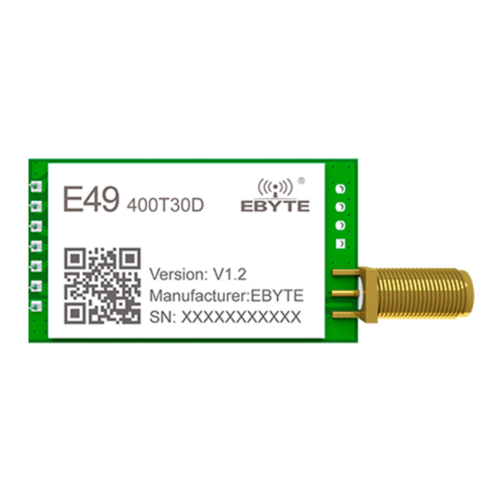
- Page 1 E49-400T30D Specifications 433MHz Plug-In Wireless Module...
-
Page 2: Table Of Contents
6.5 S LEEP .................................12 6.6 Q UICK COMMUNICATION TEST Ⅶ INSTRUCTION FORMAT .........................13 ................................13 7.1 F ACTORY DEFAULT PARAMETERS ...............................13 7.2 R EADING OF WORKING PARAMETERS ................................13 7.3 R EADING OF VERSION NUMBER Copyright ©2012–2019,Chengdu Ebyte Electronic Technology Co.,Ltd. - Page 3 ................................. 19 10.2 R EFLOW OLDERING URVE Ⅺ RELATED MODELS ..........................19 Ⅻ ANTENNA GUIDE ........................... 20 .................................. 20 12.1 A NTENNA RECOMMENDATION XIII BULK PACKAGING ..........................21 REVISE HISTORY ............................21 ABOUT US ..............................21 Copyright ©2012–2019,Chengdu Ebyte Electronic Technology Co.,Ltd.
-
Page 4: Ⅰ Overview
E49-400T30D supports a maximum transmit power of 30dBm. Users can set lower output power to save power consumption. The module works in the 433MHz frequency band, with TTL level output, and is compatible with 3.3V IO port voltage. -
Page 5: Ⅱ Specifications
The maximum capacity of a single package, it will Subcontracting method 54 Btye be automatically sub-packaged when it exceeds. Cache capacity 500 Btye Modulation method GFSK Communication Interface UART serial port Packaging method Plug-in Interface 1.27mm Copyright ©2012–2019,Chengdu Ebyte Electronic Technology Co.,Ltd. -
Page 6: Ⅲ Dimensions And Pin Definitions
It is used to indicate the working status of the module; the user wakes up the external MCU, and outputs a low level during the power-on self-test initialization; it can be configured as open-drain output or Output push-pull output, see parameter settings for details. (can be left floating) Copyright ©2012–2019,Chengdu Ebyte Electronic Technology Co.,Ltd. -
Page 7: Ⅳ Recommended Wiring Diagram
AUX outputs the high level, and starts to work normally according to the working mode formed by the combination of M1 and M0. Therefore, the user needs to wait for the rising edge of AUX as the starting point Copyright ©2012–2019,Chengdu Ebyte Electronic Technology Co.,Ltd. -
Page 8: Aux Detailed Explanation
After the module receives the serial port data, it will pull down AUX immediately and start sending data wirelessly. After all data is sent, pull up AUX again. 5.2.3 Resetting and exiting sleep mode Only at reset and when exiting sleep mode Copyright ©2012–2019,Chengdu Ebyte Electronic Technology Co.,Ltd. -
Page 9: Aux Notes
When the user enters other modes from mode 3 (sleep mode) or during the reset process, the module will reset the user parameters, during which AUX outputs a low level. 5.3.5 Detailed explanation of fixed-point mode Copyright ©2012–2019,Chengdu Ebyte Electronic Technology Co.,Ltd. -
Page 10: Broadcast Transmission
Example: Set the address of module A to 0xFFFF and the channel to 0x04. When module A is used as a receiver, it can receive all the data under the 0x04 channel to achieve the purpose of monitoring. Copyright ©2012–2019,Chengdu Ebyte Electronic Technology Co.,Ltd. -
Page 11: Ⅵ Operating Mode
This operation mode is very flexible and efficient. It is completely designed according to the user's MCU operation convenience, and can reduce the workload of the entire system as much as possible, improve system efficiency, and reduce power consumption. Copyright ©2012–2019,Chengdu Ebyte Electronic Technology Co.,Ltd. -
Page 12: Transmission Mode (Mode 0)
When entering other modes from the setting mode, the module will reconfigure the parameters. During the configuration process, AUX remains low; note After completion, it outputs a high level, so it is recommended that the user detect the rising edge of AUX. Copyright ©2012–2019,Chengdu Ebyte Electronic Technology Co.,Ltd. -
Page 13: Sleep Mode (Mode 3)
Plug in the mode selection jumper cap on the USB test board (ie M1=0, M0=0), Select 5V (module supports 2.6~5.5V). Run the "Serial port debugging assistant" software, select the correct serial port number, and observe the sending window and the corresponding receiving window. Copyright ©2012–2019,Chengdu Ebyte Electronic Technology Co.,Ltd. -
Page 14: Ⅶ Instruction Format
The module will return the current configuration parameters, such as: C3 49 xx yy; 49 here represents the module model (E49 series), xx is the version number, and yy refers to other features of the module (users can ignore). 7.4 Parameter setting instructions serial name description remark Copyright ©2012–2019,Chengdu Ebyte Electronic Technology Co.,Ltd. - Page 15 It is not recommended to use low power transmission, and its power utilization efficiency is not high. For example (the meaning of the serial number 3 "SPED" byte): the binary bit of the byte Copyright ©2012–2019,Chengdu Ebyte Electronic Technology Co.,Ltd.
- Page 16 Chengdu Ebyte Electronic Technology Co.,Ltd. E49-400T30D Specifications Specific value (user configuration) meaning Serial check bit 8N1 Serial port baud rate is 9600 Air rate is 2.4k corresponding hexadecimal Copyright ©2012–2019,Chengdu Ebyte Electronic Technology Co.,Ltd.
-
Page 17: Ⅷ Hardware Design
The antenna must not be installed inside the metal shell, which will greatly reduce the transmission distance. Copyright ©2012–2019,Chengdu Ebyte Electronic Technology Co.,Ltd. -
Page 18: Ⅸ Common Problem
If the power supply is not ideal, it may also cause garbled characters. Be sure to ensure the reliability of the power supply; Poor quality or too long extension lines and feeders will also cause a high bit error rate; Copyright ©2012–2019,Chengdu Ebyte Electronic Technology Co.,Ltd. -
Page 19: Ⅹ Welding Work Guide
220-235℃ 230-250℃ Aveage ramp-down rate(Tp to Tsmax) average rate of descent 6℃/second max 6℃/second max Time from 25°C to peak Time 25℃ to peak temperature 6 minutes max 8 minutes max temperature Copyright ©2012–2019,Chengdu Ebyte Electronic Technology Co.,Ltd. -
Page 20: Reflow Soldering Curve
10.2 Reflow Soldering Curve Ⅺ Related models carrier transmit test Product air speed Packag Product number Chip frequency power distance Size Antenna form e form 433M 1.2k~200k Plugin 26 * 16 IPEX/stamp hole E49-400T30S Copyright ©2012–2019,Chengdu Ebyte Electronic Technology Co.,Ltd. -
Page 21: Ⅻ Antenna Guide
Ultra-short straight, TX433-JZ-5 433M SMA-J 52mm antenna omnidirectional antenna Suction cup antenna, high TX490-XP-100 sucker antenna 490M SMA-J 12cm 100cm gain glue stick Ultra-short straight, TX490-JZ-5 490M SMA-J 50mm antenna omnidirectional antenna Copyright ©2012–2019,Chengdu Ebyte Electronic Technology Co.,Ltd. -
Page 22: Bulk Packaging
Revise history Version Revise date Revise instruction Maintainer About us hotline:4000-330-990 company phone :028-61399028 technical support:support@cdebyte.com official website: www.ebyte.com company address: B333-D347, Innovation Center, No. 4 Xixin Avenue, High-tech West District, Chengdu, Sichuan Province Copyright ©2012–2019,Chengdu Ebyte Electronic Technology Co.,Ltd. - Page 23 Chengdu Ebyte Electronic Technology Co.,Ltd. E49-400T30D Specifications Copyright ©2012–2019,Chengdu Ebyte Electronic Technology Co.,Ltd.