Advertisement
Available languages
Available languages
Quick Links
US
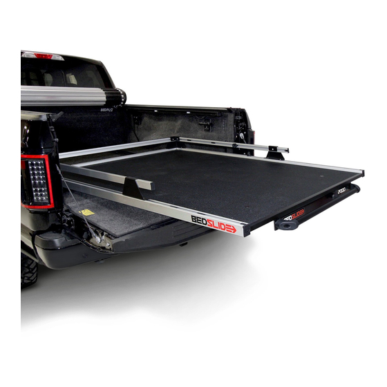
INSTALLATION INSTRUCTIONS-BEDSLIDE®
FORD F250 SUPERDUTY
KIT CONTENTS
A
BEDSLIDE®
C
GUARDRAIL KIT
(2) CORNER TOWERS
(2) GUARDRAILS
E
ADDITIONAL HARDWARE-8' APPLICATIONS ONLY!
(6) MOUNT BLOCKS
(6) 1/4-20 X 3/4 BUTTON HEAD BOLTS
(2) SIDE TOWERS
NOTE: Ensure truck bed is clean and free of any cargo prior to installation.
TORQUE WRENCH
½" RATCHET
NOTE: READ INSTRUCTIONS COMPLETELY BEFORE ATTEMPTING INSTALLATION.
Rev. 1
1/19
8.28.19
(2) SIDE TOWERS
(1) HEAD RAIL
TOOLS REQUIRED
9/16" WRENCH
7/16" WRENCH
EP-24 TORX SOCKET
B
NO DRILL BRACKETS
D
HARDWARE KIT
(18) MOUNT BLOCKS
(14) 1/4-20 X 3/4 BUTTON HEAD BOLTS
(4) D-RING TIE DOWNS
(8) 3/8-18 HEX NUTS
(1) LOCKTITE® PACKET
(2) CARABINERS
(2) SAFETY STRAPS
(2) CAB SIDE DIE ELECTRIC PADS
(2) MID GATE DIE ELECTRIC PADS
EP-24
1/8 ALLEN KEY
5/32 ALLEN KEY
BEDSLIDE.COM | 888.807.0099
Heavy!
Team Lift!
TEAM LIFT
REQUIRED
Caution
Loctite 242
Discard
(2) CAB END BRACKETS
(2) MID GATE BRACKETS
5/16 ALLEN KEY
UTILITY KNIFE
Advertisement

Related Manuals for Ford BEDSLIDE


Summary of Contents for Ford BEDSLIDE
- Page 1 NOTE: Ensure truck bed is clean and free of any cargo prior to installation. TOOLS REQUIRED EP-24 TORQUE WRENCH ½” RATCHET 9/16” WRENCH 7/16” WRENCH EP-24 TORX SOCKET 1/8 ALLEN KEY 5/32 ALLEN KEY 5/16 ALLEN KEY UTILITY KNIFE NOTE: READ INSTRUCTIONS COMPLETELY BEFORE ATTEMPTING INSTALLATION. Rev. 1 1/19 8.28.19 BEDSLIDE.COM | 888.807.0099...
- Page 2 Attach bar handle to the front of the frame by using the pre-installed 3/8-16 x 1 ½” socket cap bolts located on the front faceplate. Tighten each socket cap bolt using a 5/16 allen key. PLEASE NOTE: The bar handle is located underneath the decks between the frame. 5/16 ALLEN KEY 2/19 BEDSLIDE.COM | 888.807.0099...
- Page 3 Secure using the supplied 1/4-20 x 3/4” allen head bolts in to the MOUNT BLOCKS with a 5/32 allen key. TIGHTEN TO MANUFACTURE SPECS, 10 FT. LBS. REAR BEDTRAX (HANDLE END) 1/8 ALLEN KEY 5/32 ALLEN KEY 3/19 BEDSLIDE.COM | 888.807.0099...
- Page 4 Secure the CORNER TOWER to the BEDTRAX with (2) supplied 1/4-20 x 3/4” allen head bolts with a 5/32 allen key. TIGHTEN TO MANUFACTURE SPECS, 10 FT. LBS. 5/32 ALLEN KEY 4/19 BEDSLIDE.COM | 888.807.0099...
- Page 5 TOWER and secure them to the BEDTRAX with the supplied 1/4-20 x 3/4” allen head bolts. DO NOT TIGHTEN!! *PLEASE NOTE: BEDSLIDE® recommends a D-ring tie down be mounted in front of and behind each of the SIDE TOWERS. Pre-install them before fastening the SIDE TOWERS.
- Page 6 BEDTRAX, position at desired location and tighten down. Lastly re-install the (2) plastic end caps and tighten the set screws with a 1/8 allen key. THAT’S IT! YOUR BEDSLIDE® IS FULLY ASSEMBLED! 1/8 ALLEN KEY TIGHTEN TO MANUFACTURE SPECS, 15 INCH LBS.
- Page 7 TOWER and secure them to the BEDTRAX with the supplied 1/4-20 x 3/4” allen head bolts. DO NOT TIGHTEN!! *PLEASE NOTE: BEDSLIDE® recommends a D-ring tie down be mounted in front of and behind each of the SIDE TOWERS. Pre-install them before fastening the SIDE TOWERS.
- Page 8 BEDTRAX, position at desired location and tighten down. Lastly re-install the (2) plastic end caps and tighten the set screws with a 1/8 allen key. THAT’S IT! YOUR BEDSLIDE® IS FULLY ASSEMBLED! 1/8 ALLEN KEY TIGHTEN TO MANUFACTURE SPECS, 15 INCH LBS.
- Page 9 INSTALLATION SEPARATE SLIDING TOP FRAME FROM THE BASE Fully extend the BEDSLIDE® and remove the top frame by lifting up and out. The welded safety stops must go up and over the rear roller bearings and spacer guides in order for the top frame to release.
- Page 10 DO NOT REMOVE ALL 4 BED BOLTS AT ONCE! Removal of all 4 bed bolts will allow the bed to move out of alignment. This will make it difficult to re-install the bed bolts. TOP VIEW EP-24 EP-24 TORX SOCKET UTILITY KNIFE 10/19 BEDSLIDE.COM | 888.807.0099...
- Page 11 Pull a corner of the die-electric tape and apply a piece to the underside of each bracket. Stick the tape to the ends that will be bolted down the bed. Failure to use the die-eletric tape may result in galvanic corrosion! CAB SIDE BRACKETS MID GATE BRACKETS 11/19 BEDSLIDE.COM | 888.807.0099...
- Page 12 SECURE FRONT (CAB END) MOUNTING BRACKETS TO THE BED Apply a small bead of Loctite® 242 to the threads of the new factory bed bolts and secure both the LEFT and RIGHT mounting brackets directly to the bed. DO NOT TIGHTEN!! 12/19 BEDSLIDE.COM | 888.807.0099...
- Page 13 DO NOT REMOVE ALL 4 BED BOLTS AT ONCE! Removal of all 4 bed bolts will allow the bed to move out of alignment. This will make it difficult to re-install the bed bolts. TOP VIEW EP-24 EP-24 TORX SOCKET UTILITY KNIFE 13/19 BEDSLIDE.COM | 888.807.0099...
- Page 14 Apply a small bead of Loctite® 242 to the threads of the new factory bed bolts and secure both the LEFT and RIGHT mounting brackets directly to the bed. TIGHTEN ALL FOUR FACTORY BED BOLTS TO 129 FT. LBS. TO SECURE THE BEDSLIDE® IN PLACE. EP-24...
- Page 15 INSTALLATION RE-INSTALL SLIDING TOP FRAME Re-install the BEDSLIDE® top frame into the base by placing top frame over the rear bearings and sliding the frame forward to the stowed position. This step will require 2 people to help lift! slide...
- Page 16 & right of the bed. Once positioned tighten the bolts with a 5/32 allen key and 7/16 wrench. TIGHTEN TO MANUFACTURE SPECS, 10 FT. LBS. 5/32 ALLEN KEY 7/16” WRENCH 16/19 BEDSLIDE.COM | 888.807.0099...
- Page 17 See fig.1. Lastly, secure each carabiner to the restraint tabs located on the passenger and driver side. See fig 2. THE SAFETY STRAP MUST BE UNCLIPPED EACH TIME THE BEDSLIDE® IS EXTENDED. FAILURE TO DO SO AND THE UNIT WILL NOT RELEASE. RE-INSTALL WHEN BEDSLIDE® IS RETRACTED. FIG. 1 That’s it! Your BEDSLIDE®...
- Page 18 If the film comes up with a letter attached, position back in place and rub with a card such as a bank card or even your hand so the decal adheres to the surface of the tie down rail. 18/19 BEDSLIDE.COM | 888.807.0099...
- Page 19 OPERATION PROPER BEDSLIDE OPERATION Proper operation will ensure many years of great service from your BEDSLIDE®. Below are 3 easy steps for proper operation: 1. Unclip safety straps 2. Pull T-handle against the grab bar 3. With both hands firmly on the bar handle, slide to desired extension 4.
- Page 21 INSTRUCTIONS D’INSTALLATION-BEDSLIDE® Lourd! Remontée FORD F250 SUPER DUTY LEVÉE D´EQUIPE d’équipe! REQUISE Mise en garde Loctite 242 Jeter CONTENU DU KIT PAS DE SUPPORTS DE FORAGE BEDSLIDE® (2) SUPPORTS DE CABINE (2) SUPPORTS DE PORTE MID KIT DE GARDE KIT DE MATÉRIEL (18) BLOCS DE MONTAGE (14) BOULONS DE TÉTE À...
- Page 22 à téte cylindrique situés sur la plaque frontale. Serrer chaque boulon à téte cylindrique à l’aide d’un Clé allen 5/16. VEUILLEZ NOTER: La poignée de la barre est située sous les ponts entre le cadre. Clé Allen 5/16 2/19 BEDSLIDE.COM | 888.807.0099...
- Page 23 Sécurisez á I´aide de I´allen 1/4-20 x 3/4” fourni boulons á téte dans les BLOCS DE MONTAGE avec une clé allen 5/32. SERRER AUX SPECIFICATIONS DE FABRICATION, 10 PI. LBS. Clé Allen 1/8 LITERIE ARRIERE (POIGNEE) Clé Allen 5/32 3/19 BEDSLIDE.COM | 888.807.0099...
- Page 24 Fixez la TOUR DE COIN au BEDTRAX avec (2) fourni Vis á téte creuse allen de 1/4-20 x 3/4” avec clé allen 5/32. SERRER AUX SPECIFICATIONS DE FABRICATION, 10 PI. LBS. Clé Allen 5/32 4/19 BEDSLIDE.COM | 888.807.0099...
- Page 25 (2) en dessous de chaque tour et fixez-les au BEDTRAX á I´aide de I´allen fourni boulons á téte. NE PAS SERRER!! *VEUILLEZ NOTER: BEDSLIDE® recommande d´attacher les anneaux en D monté devant et derriére chacun des tours latérales. Préinstallez-les avant de fixer le TOURS LATÉRAUX.
- Page 26 DE MONTAGE vous précédemment inséré dans le BEDTRAX, positionnez-le á I´endroit souhaité et serrez-le. Enfin, réinstallez les (2) embouts en plastique et serrez les vis de blocage avec une clé allen 1/8. C´EST TOUT! VOTRE BEDSLIDE EST ENTIÉREMENT ASSEMBLÉ! Clé Allen 1/8 SERRER AUX SPECIFICATIONS DE FABRICATION, 15 POUCES DE LBS.
- Page 27 (2) en dessous de chaque tour et fixez-les au BEDTRAX à l’aide du tournevis fourni de 1/4-20 x 3/4” boulons à téte. NE PAS SERRER!! *VEUILLEZ NOTER: BEDSLIDE® recommande d’attacher les anneaux en D monté devant et derrière chacun des tours latérales. Préinstallez-les avant de fixer le TOURS LATÉRAUX.
- Page 28 BLOCKS vous précédemment inséré dans le BEDTRAX, positionnez-le à l’endroit souhaité et serrez-le. Enfin, réinstallez les (2) embouts en plastique et serrez les vis de réglage avec une clé allen 1/8. C’EST TOUT! VOTRE BEDSLIDE® EST ENTIÈREMENT ASSEMBLÉ! Clé Allen 1/8 SERRER AUX SPECIFICATIONS DE FABRICATION, 15 POUCES LBS.
- Page 29 Si votre lit est équipé d´un spray dans la doublure de lit, vous devez couper et enlever le materiau autour du boulon de lit. Un carré de 3 1/2”x 3 ½”suffit. 3 1/2” Couteau tout usage 9/19 BEDSLIDE.COM | 888.807.0099...
- Page 30 NE RETIREZ PAS LES 4 BOULONS DE LIT Á LA FOIS! Le retrait des 4 boulons du lit permettra au lit de sortir de son alignement. Cela rendra difficile la réinstallation des boulons du lit. VUE DE DESSUS EP-24 EP-24 TORX SOCKET COUTEAU TOUT USAGE 10/19 BEDSLIDE.COM | 888.807.0099...
- Page 31 Tirez un coin du ruban adhésif et appliquez un morceau sur le dessous de chaque support. Collez le ruban aux extrémités qui seront boulonnées dans le lit. NE PAS UTILISER LE RUBAN ADHÉSIF PEUT ENTRAINER UNE CORROSION GALVANIQUE! SUPPORTS LATÉRAUX SUPPORTS DE PORTE MID 11/19 BEDSLIDE.COM | 888.807.0099...
- Page 32 SUPPORTS DE MONTAGE SECURISES SUR LE LIT Appliquez une petite perle de Loctite® 242 sur le filetage des nouveaux boulons d’assemblage et fixez les deux supports de montage gauche et droite directement sur le lit. NE PAS SERRER!! 12/19 BEDSLIDE.COM | 888.807.0099...
- Page 33 Ne retirez pas les 4 boulons de lit à la fois! Rle retrait des 4 boulons du lit permettra au lit de sortir de son alignement. Cela rendra difficile la réinstallation des boulons du lit. VUE DE DESSUS EP-24 DOUILLE TORX EP-24 COUTEAU TOUT USAGE 13/19 BEDSLIDE.COM | 888.807.0099...
- Page 34 Appliquez une petite perle de Loctite® 242 sur les filets des nouvelles vis d’assemblage et fixez les deux les supports de montage GAUCHE et DROIT directement sur le lit. TSERRE TOUTES LES BOULONS DE QUATRE FACTORY LITS À 129 PI. LBS. POUR SÉCURISER LE BEDSLIDE® EN PLACE. EP-24 DOUILLE TORX EP-24 14/19 BEDSLIDE.COM | 888.807.0099...
- Page 35 INSTALLATION RÉINSTALLER LE CADRE SUPÉRIEUR COULISSANT Réinstallez le cadre supérieur BEDSLIDE® dans la base en placant le cadre supérieur sur les roulements arrière. Et en glissant le cadre vers l’avant en position repliée. Cette étape nécessitera 2 personnes pour aider à soulever! Faire glisser VUE DE CÓTÉ...
- Page 36 90 degrés afin que les languettes soient tournées vers la gauche et la droite du lit. Une fois positionnés serrer les boulons avec une clé allen 5/32 et une clé 7/16. SERRER AUX SPECIFICATIONS DE FABRICATION, 10 PI. LBS. Clé Allen 5/32 Clé 7/16” 16/19 BEDSLIDE.COM | 888.807.0099...
- Page 37 Voir fig. 1 Enfin, fixez chaque mousqueton aux languettes de retenue situées sur le passager et cóté conducteur. Voir la figure 2. LA SANGLE DE SÉCURITÉ DOIT ÉTRE DÉCLARÉE CHAQUE MOMENT LE BEDSLIDE® EST ÉTENDU. LE DÉFAUT DE LE FAIRE ET L´APPAREIL NE SERA PAS LIBÉRÉ. RÉINSTALLEZ QUAND BEDSLIDE®...
- Page 38 Si le film contient une lettre, replacez-le et frottez-le avec une carte telle qu´une carte bancaire ou méme votre main pour que le décalque adhére á la surface du rail d´arrimage. 18/19 BEDSLIDE.COM | 888.807.0099...
- Page 39 Ne pas opérer sur des pentes raides! Si vous ne le faites pas, vous risquez un glissement incontróle si le véhicule est en pente. Utilisez des sangles de sécurité lorsque BEDSLIDE® est en position rétractée. Ne chargez pas le BEDSLIDE® au-delá de sa capacité de poids! Une surcharge de I´unité...
- Page 41 INSTRUCCIONES DE INSTALACIÓN-BEDSLIDE® ¡Pesado! ¡Equipo de EQUIPO DE FORD F250 SUPERDUTY ELEVACIÓN elevación! Precaución Loctite 242 Desechar CONTENIDO DEL KIT SOPORTES BEDSLIDE® (2) SOPORTES DE CABINA (2) SOPORTES DE PUERTA MEDIA KIT DE BARANDAS KIT DE HARDWARE (18) BLOQUES DE MONTAJE (14) PERNOS DE CABEZA DE BOTÓN 1/4-20 X 3/4...
- Page 42 Apriete cada perno de la tapa del zócalo con una llave allen 5/16. TENGA EN CUENTA: El mango de la barra se encuentra debajo de las cubiertas entre el marco. LLAVE ALLEN 5/16 2/19 BEDSLIDE.COM | 888.807.0099...
- Page 43 Asegúre usando un tornillo allen 1/4-20 x 3/4” suministrados en los bloques de montaje con una llave allen de 5/32. APRIETE A 10 LIBRAS-PIES POR ESPECIFICACIONES DE LA FABRICA BEDTRAX (LADO POSTERIOR) LLAVE ALLEN 1/8 LLAVE ALLEN 5/32 3/19 BEDSLIDE.COM | 888.807.0099...
- Page 44 Asegure la TORRE DE ESQUINA al BEDTRAX con (2) tornillos de cabeza allen de 1/4-20 x 3/4” con una llave allen 5/32. APRIETE A 10 LIBRAS-PIES POR ESPECIFICACIONES DE LA FABRICA LLAVE ALLEN 5/32 4/19 BEDSLIDE.COM | 888.807.0099...
- Page 45 1/4-20 x 3/4”. ¡NO LOS APRIETE! TENGA EN CUENTA: BEDSLIDE recomienda un amarre de anillo en D para ser montado delante y detrás de cada una de las TORRES LATERALES. Preinstálelas antes de sujetar las TORRES LATERALES.
- Page 46 Por último, vuelva a instalar las (2) tapas de plástico y apriete los tornillos de fijación con una llave allen de 1/8. ¡ESO ES! ¡TU BEDSLIDE ESTÁ TOTALMENTE MONTADO! LLAVE ALLEN 1/8 APRIETE A LAS ESPECIFICACIONES DE FÁBRICA, 15 PULGADAS DE LIBRAS.
- Page 47 MONTAJE debajo de cada TORRE y asegurelas al BEDTRAX con el allen de 1/4-20 x 3/4” suministrado tornillos de cabez. NO APRIETE! *TENGA EN CUENTA: BEDSLIDE® recomienda un ammare de anillo D montado delante y detrás de cada una de las TORRES LATERALES. Preinstale antes de fijar las TORRES LATERALES.
- Page 48 Por último, vuelva a instalar las (2) tapas de plástico y apriete los tornillos de fijación con una llave allen de 1/8. ¡ESO ES! ¡TU BEDSLIDE ESTÁ TOTALMENTE MONTADO! LLAVE ALLEN 1/8 APRIETE A LAS ESPECIFICACIONES DE FÁBRICA, 15 PULGADAS DE LIBRAS.
- Page 49 INSTALACIÓN SEPARAR MARCO SUPERIOR DESLIZANTE DE LA BASE Extienda completamente el BEDSLIDE® y retire el marco superior levantándolo hacia arriba y hacia afuera. Los topes de seguridad soldados deben ir hacia arriba y sobre los cojinetes de rodillos traseros y el espaciador. Guias para que el marco superior se suelte.
- Page 50 La eliminación de los 4 pernos de la cama permitara que la cama se mueva fuera de alineación. Esto hará que se dificil volver a instalar los pernos de la cama. VISTA SUPERIOR EP-24 ENCHUFE TORX EP-24 CUCHILLO 10/19 BEDSLIDE.COM | 888.807.0099...
- Page 51 Ptire de una esquina de la cinta eléctrica y aplique una pieza en la parte inferior de cada soporte. Pegue la cinta en los extremos que se atornillarán a la cama. Si no usa la cinta die-electric puede provocar corrosión galvánica! SOPORTES LATERALES DE LA CABINA SOPORTES DE PUERTA MEDIA 11/19 BEDSLIDE.COM | 888.807.0099...
- Page 52 SEGURE LOS SOPORTES DE MONTAJE FRONTAL (CABINA) Aplique una pequeña cuenta de Loctite® 242 a las roscas de los nuevos pernos de cama y asegure los soportes de montaje IZQUIERDA y DERECHA directamente a la cama. ¡NO LOS APRIETE! 12/19 BEDSLIDE.COM | 888.807.0099...
- Page 53 ¡NO QUITE LOS 4 PERNOS DE CAMA EN UNA VEZ! La eliminación de los 4 pernos permitirá la cama para moverse fuera de alineación. Esto hará que sea dificil volver a instalar los pernos de la cama. VISTA SUPERIOR EP-24 ENCHUFE TORX EP-24 CUCHILLO 13/19 BEDSLIDE.COM | 888.807.0099...
- Page 54 Aplique una pequena cuenta de Loctite 242® a las roscas de los nuevos pernos de cama y asegure los soportes de montaje IZQUIERDO y DERECHO directamente a la cama. APRIETE LOS CUATRO PERNOS DE CAMA A 129 PIES LB. PARA ASEGURAR EL BEDSLIDE® EN SU LUGAR.
- Page 55 INSTALACIÓN VUELVA A INSTALAR EL MARCO SUPERIOR DESLIZANTE Reinstale el marco superior BEDSLIDE® en la base colocando el marco superior sobre los cojinetes traseros y deslizando el marco hacia adelante a la posición replegada. Este paso requerirá 2 personas para ayudar a levantar!
- Page 56 Una vez colocados apretar los tornillos con una llave allen 5/32 y una llave 7/16. APRIETE A ESPECIFICACIONES DE LA FáBRICA , 10 PIES LIBRAS LLAVE ALLEN 5/32 LLAVE 7/16 16/19 BEDSLIDE.COM | 888.807.0099...
- Page 57 Ver fig. 2. LA CORREA DE SEGURIDAD DEBE ESTAR DESCENDIDA CADA VEZ QUE SE EXTIENDE LA BEDSLIDE®. NO HACERLO Y LA UNIDAD NO SE LANZARÁ. VUELVA A INSTALAR CUANDO LA BEDSLIDE® SE RETIRA. FIG. 1 ¡Eso es! ¡Tu instalación de BEDSLIDE®...
- Page 58 Si la cinta protectora aparece con una letra adjunta, vuelva a colocarla en su logar y frote con una tarjeta como una tarjeta bancaria o incluso su mano para que la calcomania se adhiera a la superficie del carril de amarre. 18/19 BEDSLIDE.COM | 888.807.0099...
- Page 59 ¡No operar en pendientes pronunciadas! De lo contrario, se puede producir un deslizamiento fuera de control se el vehiculo está en una pendiente. Utilice correas de seguridad cuando la BEDSLIDE® esté en posición retraida. ¡No cargue la BEDSLIDE® más allá de sus capacidad de peso! La sobrecarga de la unidad puede danar el marco de acero o los rodamientos.
Need help?
Do you have a question about the BEDSLIDE and is the answer not in the manual?
Questions and answers