
Related Manuals for ASROCK iEPF-9000S-EX4


Summary of Contents for ASROCK iEPF-9000S-EX4
- Page 1 User Manual Version 1.0 Published August 2022 Copyright©2022 ASRockInd INC. All rights reserved.
- Page 2 In no event shall ASRock Rack, its directors, officers, employees, or agents be liable for any indirect, special, incidental, or consequential damages (including damages for loss of profits, loss of business, loss of data, interruption of business and the like), even if ASRock Rack has been advised of the possibility of such damages arising from any defect or error in the documentation or product.
- Page 3 Important Safety Instructions For user safety, please read and follow all instructions, Warnings, Cautions, and Notes marked in this manual and on the associated device before handling/ operating the device, to avoid injury or damage. 1. Read these safety instructions carefully. 2.
- Page 4 AC adapter provided with the product, a replacement AC adapter provided by ASRock Industrial or agency, or an AC adapter purchased as an accessory from ASRock Industrial or agency should be used with the product.
- Page 5 Replaceable Batteries CAUTION RISK OF EXPLOSION IF BATTERY IS REPLACED BY AN INCORRECT TYPE. DISPOSE OF USED BATTERIES ACCORDING TO THE INSTRUCTIONS CAUTION The equipment is equipped with a battery-powered real-time clock circuit. There is a risk of explosion if a battery is incorrectly replaced. Replace only with the same or equivalent type as designated by the manufacturer.
- Page 6 Contact Information If you need to contact ASRock Industrial or want to know more about ASRock Industrial, you’re welcome to visit ASRock Industrial’s website at www.asrockind.com ; or you may contact your dealer for further information. ASRock Industrial Incorporation Email: Info_ipc@asrockind.com...
-
Page 7: Table Of Contents
Contents Chapter 1 Introduction Key Features Package List Specifications Dimensions Block Diagram Chapter 2 System Overview System Front Panel 2.1.1 Control Panel Buttons and LED Indicators 2.1.2 I/O Connectors HDD Panel Drive Tray LEDs Chapter 3 Hardware Installation and Maintenance How to Install the Hard Disk Drive How to Install the SIM Card How to Disassemble the System... - Page 8 Advanced Screen 5.3.1 CPU Configuration 5.3.2 Chipset Configuration 5.3.3 Storage Configuration 5.3.4 Super IO Configuration 5.3.5 ACPI Configuration 5.3.6 USB Configuration 5.3.7 Trusted Computing Hardware Health Event Monitoring Screen Security Screen Boot Screen Exit Screen...
-
Page 9: Chapter 1 Introduction
In case any modifications of this documentation occur, the updated version will be available on ASRock Industrial’s website without further notice. If you require technical support related to this product, please visit our website for specific information about the model you are using. - Page 10 iEP-9000E • Intel® 10 Gen Xeon® W or Core™ Processors with W480E Chipset • 4 x 260-pin DDR4 SO-DIMM up to 128GB (32GB per DIMM) • 1 x M.2 Key M, 1 x M.2 Key B, 1 x M.2 Key E, 2 x Mini PCIe • 4 x USB 3.2 Gen2x1, 2 x USB 2.0, 6 x COM, 4 x SATA3, 8 x DI, 8 x DO • 5 x Intel Gigabit LAN (2 support PoE) • Supports Triple Display, 2 x Displayport, 1 x VGA...
-
Page 11: Package List
/ iEPF-9002S-EX4 / iEP-9000E / iEP-9002E 1.2 Package List Item Quantity iEPF-9000S Series / iEP-9000E Series Rubber foot M3x8L Round Head Bolts for Rubber foot Desk Mount M3x5L Countersunk Screws for Desk Mount M4x10L Round Head Bolts for Desk Mount M3x4L Round Head Bolts for SODIMM Bracket Terminal Block 1X3P ST 7.62m... - Page 12 We recommend that 330W adapter (Certified adapter, Output: 24Vdc,13.75A) is used if there is no PCIe or PCI add-on cards assembled on the iEPF-9000S-EX4. Users may use a DC source instead of the optional 330W adapter (Certified adapter, Output: 24Vdc,13.75A) when power consumption is over 330W in an environment where the...
-
Page 13: Specifications
/ iEPF-9002S-EX4 / iEP-9000E / iEP-9002E 1.3 Specifications iEPF-9000S-EX4 Processor System Intel Gen Xeon W or Core™ Processors ® ® Chipset Intel W480E ® Socket LGA 1200 Memory Technology Dual Channel DDR4 2933 / 2666 / 2400 / 2133 MHz... - Page 14 Storage 1 x M.2 (Key M, 2280) with PCIe Gen3 x4 (shared with PCIe x4 slot) or SATA3 for SSD SATA 4 x SATA3 (6Gb/s), support RAID 0/1/5/10 4 x 2.5" HDD/SSD Tray CFast (Option) 1 x Type II socket (Shared with SATA3) Rear I/O DisplayPort Ethernet...
- Page 15 / iEPF-9002S-EX4 / iEP-9000E / iEP-9002E iEPF-9002S-EX4 Processor System Intel Gen Core™ Processors ® Chipset Intel H420E ® Socket LGA 1200 Memory Technology Dual Channel DDR4 2933 / 2666 / 2400 MHz, - Intel Core i9 / i7 CPUs support DDR4 up to 2933 MHz...
- Page 16 Storage 1 x M.2 (Key M, 2280) with SATA3 for SSD SATA 2 x SATA3 (6Gb/s) 2 x 2.5" HDD/SSD Tray Rear I/O DisplayPort Ethernet 3 x 1 Gigabit LAN 4 x USB 3.2 Gen1x1, 2 x USB2.0, 1 x USB2.0 internal connector w/ lock function Audio 1 x Mic-in, 1 x Line-out 4 x RS232/422/485...
- Page 17 / iEPF-9002S-EX4 / iEP-9000E / iEP-9002E iEP-9000E Processor System Intel 10th Gen Xeon W or Core™ Processors ® ® Chipset Intel ® W480E Socket LGA 1200 Memory Technology Dual Channel DDR4 2933 / 2666 / 2400 / 2133 MHz...
- Page 18 Rear I/O DisplayPort Ethernet 5 x 1 Gigabit LAN 4 x USB 3.2 Gen2x1, 2 x USB2.0, 1 x USB2.0 internal connector w/ lock function Audio 1 x Mic-in, 1 x Line-out 4 x RS232/422/485 2 x RS232 8DIs/8DOs Watchdog Timer Output From Super I/O to drag RESETCON# Interval...
- Page 19 / iEPF-9002S-EX4 / iEP-9000E / iEP-9002E iEP- 9002E Processor System Intel 10th Gen Core™ Processors ® Chipset Intel H420E ® Socket LGA 1200 Memory Technology Dual Channel DDR4 2933 / 2666 / 2400 MHz, - Intel Core i9 / i7 CPUs support DDR4 up to 2933 MHz...
- Page 20 Rear I/O DisplayPort Ethernet 3 x 1 Gigabit LAN 4 x USB 3.2 Gen1x1, 2 x USB2.0, 1 x USB2.0 internal connector w/ lock function Audio 1 x Mic-in, 1 x Line-out 4 x RS232/422/485 2 x RS232 8DIs/8DOs Watchdog Timer Output From Super I/O to drag RESETCON# Interval...
-
Page 21: Dimensions
/ iEPF-9002S-EX4 / iEP-9000E / iEP-9002E 1.4 Dimensions iEPF-9000S-EX4 / iEPF-9002S-EX4 Front View - iEPF-9000S-EX4 Front View - iEPF-9002S-EX4... - Page 22 Top View Left-Side View...
- Page 23 / iEPF-9002S-EX4 / iEP-9000E / iEP-9002E Right-Side View Rear Side View...
- Page 24 Bottom View...
- Page 25 / iEPF-9002S-EX4 / iEP-9000E / iEP-9002E iEP-9000E / iEP- 9002E Front View - iEP-9000E Front View - iEP- 9002E...
- Page 26 Top View Left-Side View...
- Page 27 / iEPF-9002S-EX4 / iEP-9000E / iEP-9002E Right-Side View Rear Side View...
- Page 28 Bottom View...
-
Page 29: Block Diagram
/ iEPF-9002S-EX4 / iEP-9000E / iEP-9002E 1.5 Block Diagram iEPF-9000S-EX4 iEPF-9000S-EX4 Block Diagram... - Page 30 iEPF-9002S-EX4 iEPF-9002S-EX4 Block Diagram...
- Page 31 / iEPF-9002S-EX4 / iEP-9000E / iEP-9002E iEP-9000E iEP-9000E Block Diagram...
- Page 32 iEP-9002E iEP-9002E Block Diagram...
-
Page 33: Chapter 2 System Overview
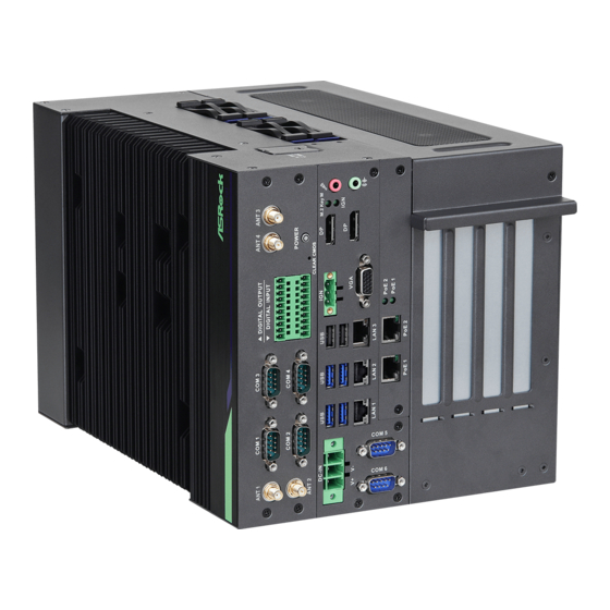
/ iEPF-9002S-EX4 / iEP-9000E / iEP-9002E Chapter 2 System Overview This chapter provides diagrams showing the location of important components of the system system. 2.1 System Front Panel 10 11 Description Antenna Port 1 Serial Port (COM 2) Serial Port (COM 1) - Page 34 Remote Power On/Off Switch (IGN) 2 x USB 2.0 Ports (H610 sku) VGA Port PoE1 Port Status LED (PoE 1) PoE2 Port Status LED (PoE 2) LAN RJ-45 PoE Port (PoE 2) (W480E sku) LAN RJ-45 Port (LAN 3) LAN RJ-45 PoE Port (PoE 1) (W480E sku) LAN RJ-45 Port (LAN 2) LAN RJ-45 Port (LAN 1) 4 x USB 3.2 Gen2x1 Ports (W480E sku)
-
Page 35: Control Panel Buttons And Led Indicators
/ iEPF-9002S-EX4 / iEP-9000E / iEP-9002E 2.1.1 Control Panel Buttons and LED Indicators Power Switch Press the power switch button to toggle the system power-on and power-off modes. To remove all power from the system completely, disconnect the power cord from the system. - Page 36 M.2 Slot (Key M) Status LED Status Description Blinking Green M.2 Slot (Key M) on the motherboard is populated with a M.2 module. Empty M.2 Slot (Key M) IGN Status LED Status Description Solid Green The IGN connector is connected and working normally. No connection...
-
Page 37: I/O Connectors
/ iEPF-9002S-EX4 / iEP-9000E / iEP-9002E 2.1.2 I/O Connectors Connector Description Antenna Port Connect the antenna cable to this connector. This system provides six COM ports through Serial Port (COM) D-sub 9-pin connectors. This system provides non-isolation digital Digital Ouput input circuits for customer's device. -
Page 38: Hdd Panel
2.2 HDD Panel iEPF-9000S Series / iEP-9000E Series Description 2.5" HDD/SSD Tray (HDD0) 2.5" HDD/SSD Tray (HDD1) 2.5" HDD/SSD Tray (HDD3) 2.5" HDD/SSD Tray (HDD2) Side Vent 2 x SIM Card Slots (SIM1 is for M.2 B key slot) System Heatsink... -
Page 39: Drive Tray Leds
/ iEPF-9002S-EX4 / iEP-9000E / iEP-9002E 2.3 Drive Tray LEDs Description HDD Power LED HDD Activity LED Status LED Definitions HDD Power LED Status Description Blue HDD powered-on No power to HDD HDD Activity LED Status Description Solid Green... -
Page 40: Chapter 3 Hardware Installation And Maintenance
Chapter 3 Hardware Installation and Maintenance This chapter helps you disassemble the system and install components. Before You Begin Before you work with the system, pay close attention to the “Important Safety Instructions” at the beginning of this manual. 1. Make sure the system is powered off. Power down the system if it is still running. -
Page 41: How To Install The Hard Disk Drive
/ iEPF-9002S-EX4 / iEP-9000E / iEP-9002E 3.1 How to Install the Hard Disk Drive Installing a Hard Disk Drive into 2.5" Hard Drive Tray The system supports hot-swappable 2.5" hard drives. Removing 2.5” Hard Drive Trays from the Chassis 1. - Page 42 Installing a 2.5” Hard Drive to the Hard Drive Tray 1. Place a 2.5" HDD into the tray with the printed circuit board side facing down. Carefully align the mounting holes in the hard drive and the tray. 2. Secure the hard drive using four screws. 3.
-
Page 43: How To Install The Sim Card
/ iEPF-9002S-EX4 / iEP-9000E / iEP-9002E 3.2 How to Install the SIM Card Installing a SIM Card into a SIM Card Slot 1. Release the screw and remove the SIM card slot cover. - Page 44 2. Insert a SIM card to the SIM car slot. SIM1 (Upper Slot): When inserting the SIM Card to the upper slot, make sure the notch on the SIM card is oriented with the gold contacts face down. SIM2 (Lower Slot): When inserting the SIM Card to the lower slot, make sure the notch on the SIM card is oriented with the gold contacts face up.
-
Page 45: How To Disassemble The System
/ iEPF-9002S-EX4 / iEP-9000E / iEP-9002E 3.3 How to Disassemble the System 1. Release all screws on the heasink side 2. Remove the heatsink.. 3. Release the screws. 4. Remove the small panel from the I/O side of the system. - Page 46 5. Remove the middle panel from the I/O side of the system. 6. Release the screws. 7. Remove the big panel from the I/O side of the system.
- Page 47 / iEPF-9002S-EX4 / iEP-9000E / iEP-9002E 8. Release the screw. 9. Push the cover toward the I/O side of the chassis to remove the cover from the locked position. Remove the cover. 10. Release the two screws from the inside of the chassis.
- Page 48 11. Remove the screws from the inside of the chassis. 12. Remove the screws from the rear side of the chassis.
- Page 49 / iEPF-9002S-EX4 / iEP-9000E / iEP-9002E 13. Pull out the motherboard tray from the system.
-
Page 50: How To Install The Desk Mount Bracket
3.4 How to Install the Desk Mount Bracket 1. Attach the two desk mount brackets to the iEPF-9000S Series or iEP-9000E Series and secure them with eight screws. iEPF-9000S Series iEP-9000E Series 2. Then you can attach the iEPF-9000S Series or iEP-9000E Series to any horizontal surface. -
Page 51: How To Install The Rubber Foot
/ iEPF-9002S-EX4 / iEP-9000E / iEP-9002E 3.5 How to Install the Rubber Foot 1. Attach four rubber foots to the iEPF-9000S Series or iEP-9000E Series and secure them with four screws. iEPF-9000S Series iEP-9000E Series 2. Then you can put the iEPF-9000S Series or iEP-9000E Series to any horizontal surface. -
Page 52: Chapter 4 Motherboard
Chapter 4 Motherboard 4.1 Motherboard Layout Top Side... - Page 53 / iEPF-9002S-EX4 / iEP-9000E / iEP-9002E Bottom Side...
- Page 54 1 : SMBUS_TEST1 Signal Signal Signal PIN Signal Name Name Name Name SMB_DATA SMB_CLK MBUS_TEST 2 : M.2 Key-B Socket (M2_B1) 3 : PWR_BAT1 Open : Normal Short : Charge Battery 4 : SATA Connector (SATA_CON1) 5 : Clear CMOS Headers CLRMOS1 : 1-2 : Normal 2-3 : Clear CMOS...
- Page 55 / iEPF-9002S-EX4 / iEP-9000E / iEP-9002E 6 : M.2 Key-E Socket (M2_E1) 7 : ATX/AT Mode Jumper (SIO_AT1) Open : ATX Mode Short : AT Mode 8 : Chassis Intrusion Headers (CI1, CI2) CI1 : Open : Normal Short : Active Case Open...
- Page 56 9 : M.2 Key-M Socket (M2_M1) 10 : DC Input Connector (DC_IN1) 11 : Top : RJ45 LAN Port (LAN1) Bottom : USB3.2 Gen2 Ports (USB3_1_2) 12 : Top : RJ45 LAN Port (LAN2) Bottom : USB3.2 Gen2 Ports (USB3_3_4) 13 : Top : RJ45 LAN Port (LAN3) Bottom : USB2.0 Ports (USB2_5_6) 14 : POE Connector (POE_CON1)
- Page 57 / iEPF-9002S-EX4 / iEP-9000E / iEP-9002E 19 : Front Panel Audio Header MIC2_L MIC2_R OUT2_R MIC_RET J_SENS E OUT2_L OUT_RET 20 : SPDIF Header 21 : 3W Audio Output Wafer (SPEAKER1) Signal Signal Signal Signal Name Name Name Name...
- Page 58 24 : Chassis FAN Connector (+12V) FAN_SPEED_CONTROL CHA_FAN_SPEED +12V 25 : System Panel Header HDLED+ PLED+ HDLED- PLED- PWRBTN# RESET# 26 : 12V PCIe Power Connector 27 : ESPI Connector (ESPI1)
-
Page 59: Chapter 5 Uefi Setup Utility
/ iEPF-9002S-EX4 / iEP-9000E / iEP-9002E Chapter 5 UEFI Setup Utility 5.1 Introduction This section explains how to use the UEFI SETUP UTILITY to configure your system. The UEFI chip on the motherboard stores the UEFI SETUP UTILITY. You may run the UEFI SETUP UTILITY when you start up the computer. -
Page 60: Main Screen
5.1.2 Navigation Keys Please check the following table for the function description of each navigation key. Navigation Key(s) Function Description Moves cursor left or right to select Screens Moves cursor up or down to select items + / - To change option for the selected items <Enter>... -
Page 61: Advanced Screen
/ iEPF-9002S-EX4 / iEP-9000E / iEP-9002E 5.3 Advanced Screen In this section, you may set the configurations for the following items: CPU Configu- ration, Chipset Configuration, Storage Configuration, Super IO Configuration, AMT Configuration, ACPI Configuration, USB Configuration and Trusted Computing. -
Page 62: Cpu Configuration
5.3.1 CPU Configuration Intel Hyper Threading Technology Intel Hyper Threading Technology allows multiple threads to run on each core, so that the overall performace on threaded software is improved. Active Processor P-Cores Select the number of cores to enable in each processor package. CPU C States Support Enable CPU C States Support for power saving. - Page 63 / iEPF-9002S-EX4 / iEP-9000E / iEP-9002E Intel Turbo Boost Technology Intel Turbo Boost Technology enables the processor to run above its base operating frequency when the operating system requests the highest per- formance state. CPU Thermal Throttling You may select [Enabled] to enable CPU internal thermal control mechanism to keep the CPU from overheating.
-
Page 64: Chipset Configuration
5.3.2 Chipset Configuration Primary Graphics Adapter Select a primary VGA. Above 4G Decoding Enable or disable 64bit capable Devices to be decoded in Above 4G Ad- dress Space (only if the system supports 64 bit PCI decoding). VT-d ® ® Use this to enable or disable Intel VT-d technology (Intel Virtualization... - Page 65 / iEPF-9002S-EX4 / iEP-9000E / iEP-9002E Deep Sleep Configure deep sleep mode for power saving when the computer is shut down. Restore on AC/Power Loss Select the power state after a power failure. If [Power Off] is selected, the power will remain off when the power recovers.
-
Page 66: Storage Configuration
5.3.3 Storage Configuration SATA Controller(s) Use this item to enable or disable the SATA Controller feature. SATA Mode Selection Use this to select SATA mode. The default value is [AHCI Mode]. AHCI (Advanced Host Controller Interface) supports NCQ and other new features that will improve SATA disk perfor- mance but IDE mode does not have these advantages. -
Page 67: Super Io Configuration
/ iEPF-9002S-EX4 / iEP-9000E / iEP-9002E 5.3.4 Super IO Configuration COM1 Use this to set parameters of COM1. Type Select Use this to select COM1 port type: [RS232], [RS422] or [RS485]. COM2 Use this to set parameters of COM2. - Page 68 DID3 Type Select Use this to set DIO Type: [Input]. DID4 Type Select Use this to set DIO Type: [Input]. DID5 Type Select Use this to set DIO Type: [Input]. DID6 Type Select Use this to set DIO Type: [Input]. DID7 Type Select Use this to set DIO Type: [Input].
-
Page 69: Acpi Configuration
/ iEPF-9002S-EX4 / iEP-9000E / iEP-9002E 5.3.5 ACPI Configuration Suspend to RAM Use this item to select whether to auto-detect or disable the Suspend-to- RAM feature. Select [Auto] will enable this feature if the OS supports it. PCIE Devices Power On Allow the system to be waked up by a PCIE device and enable wake on LAN. -
Page 70: Usb Configuration
5.3.6 USB Configuration Legacy USB Support Use this option to enable Legacy USB support. AUTO option disables legacy support if no USB devices are connected. USB Power Control Use this option to control USB power. M.2 Key_B USB Function Use this option to enable or disable M.2 Key_B USB Function. -
Page 71: Trusted Computing
/ iEPF-9002S-EX4 / iEP-9000E / iEP-9002E 5.3.7 Trusted Computing Security Device Support Enable or disable BIOS support for security device. SHA-1 PCR Bank Use this item to enable or disable SHA-1 PCR Bank SHA256 PCR Bank Use this item to enable or disable SHA256 PCR Bank. - Page 72 Device Select Use this item to select the TPM device to be supported. TPM 1.2 will re- strict support to TPM 1.2 devices. TPM 2.0 will restrict support to TPM 2.0 devices. Auto will support both with the default set to TPM 2.0 devices. If TPM 2.0 devices are not found, TPM 1.2 devices will be enumerated.
-
Page 73: Hardware Health Event Monitoring Screen
/ iEPF-9002S-EX4 / iEP-9000E / iEP-9002E 5.4 Hardware Health Event Monitoring Screen In this section, it allows you to monitor the status of the hardware on your system, including the parameters of the CPU temperature, motherboard temperature, CPU fan speed, chassis fan speed, and the critical voltage. -
Page 74: Security Screen
5.5 Security Screen In this section, you may set, change or clear the supervisor/user password for the system. Supervisor Password Set or change the password for the administrator account. Only the ad- ministrator has authority to change the settings in the UEFI Setup Utility. Leave it blank and press enter to remove the password. -
Page 75: Boot Screen
/ iEPF-9002S-EX4 / iEP-9000E / iEP-9002E 5.6 Boot Screen In this section, it will display the available devices on your system for you to config- ure the boot settings and the boot priority. Boot Option #1 Use this item to set the system boot order. -
Page 76: Exit Screen
5.7 Exit Screen Save Changes and Exit When you select this option, it will pop-out the following message, “Save configuration changes and exit setup?” Select [OK] to save the changes and exit the UEFI SETUP UTILITY. Discard Changes and Exit When you select this option, it will pop-out the following message, “Discard changes and exit setup?”...
Need help?
Do you have a question about the iEPF-9000S-EX4 and is the answer not in the manual?
Questions and answers