Table of Contents
Advertisement
Quick Links
JANUARY 1997
TL170A
TL170AE
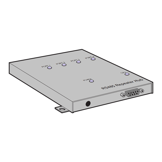
RS-485 Repeater Hub
CUSTOMER SUPPORT INFORMATION
Order toll-free in the U.S.: Call 877-877-BBOX (outside U.S. call 724-746-5500)
FREE technical support 24 hours a day, 7 days a week: Call 724-746-5500 or fax 724-746-0746
Mailing address: Black Box Corporation, 1000 Park Drive, Lawrence, PA 15055-1018
Web site: www.blackbox.com • E-mail: info@blackbox.com
Advertisement
Table of Contents

Related Manuals for Black Box TL170A


Summary of Contents for Black Box TL170A
- Page 1 Order toll-free in the U.S.: Call 877-877-BBOX (outside U.S. call 724-746-5500) FREE technical support 24 hours a day, 7 days a week: Call 724-746-5500 or fax 724-746-0746 Mailing address: Black Box Corporation, 1000 Park Drive, Lawrence, PA 15055-1018 Web site: www.blackbox.com • E-mail: info@blackbox.com...
-
Page 2: Federal Communications Commission
RS-485 REPEATER HUB FEDERAL COMMUNICATIONS COMMISSION INDUSTRY CANADA RADIO FREQUENCY INTERFERENCE STATEMENTS This equipment generates, uses, and can radiate radio-frequency energy, and if not installed and used properly, that is, in strict accordance with the manufacturer’s instructions, may cause interference to radio communication. It has been tested and found to comply with the limits for a Class A computing device in accordance with the specifications in Subpart B of Part 15 of FCC rules, which are designed to provide reasonable protection against such interference... -
Page 3: Instrucciones De Seguridad
RS-485 REPEATER HUB NORMAS OFICIALES MEXICANAS (NOM) ELECTRICAL SAFETY STATEMENT INSTRUCCIONES DE SEGURIDAD 1. Todas las instrucciones de seguridad y operación deberán ser leídas antes de que el aparato eléctrico sea operado. 2. Las instrucciones de seguridad y operación deberán ser guardadas para referencia futura. - Page 4 RS-485 REPEATER HUB 10. El equipo eléctrico deber ser situado fuera del alcance de fuentes de calor como radiadores, registros de calor, estufas u otros aparatos (incluyendo amplificadores) que producen calor. 11. El aparato eléctrico deberá ser connectado a una fuente de poder sólo del tipo descrito en el instructivo de operación, o como se indique en el aparato.
-
Page 5: Trademarks Used In This Manual
RS-485 REPEATER HUB TRADEMARKS USED IN THIS MANUAL UL is a registered trademark of Underwriters Laboratories Incorporated. Any other trademarks mentioned in this manual are acknowledged to be the property of the trademark owners. -
Page 6: Specifications
RS-485 REPEATER HUB 1. Specifications Interface — RS-485 2-wire Protocol — Asynchronous Data Rates — Up to 115,200 bps Indicators — (6) LEDs: Ports 1 through 4, Power, and CPU (5) DB9 female, (1) 5-pin Connectors — DIN power input Enclosure —... - Page 7 RS-485 REPEATER HUB TL170A: 115 VAC, 60 Hz, Power — 17 VAC (center-tapped), 20 watts; TL170AE: 230 VAC, 50 Hz, 17 VAC (center- tapped), 20 watts Size — 1.5"H x 6.75"W x 7"D (3.8 x 17.2 x 17.8 cm) Weight —...
- Page 8 RS-485 REPEATER HUB 2. Introduction The RS-485 Repeater Hub expands one RS-485 2-wire port to four RS-485 2-wire ports. The CPU port connects to your existing 2-wire multidrop line as usual, and up to four RS-485 2-wire lines may be connected to the remaining ports.
- Page 9 RS-485 REPEATER HUB to the earth ground carried to the AC wall receptacle via the wallmount transformer. Using the two tabs in the enclosure, the Hub can be mounted on a flat surface. You can also install a surge-suppressed power strip between to AC transformer and the AC line to provide additional protection to the Hub.
-
Page 10: Installation
RS-485 REPEATER HUB 3. Installation WARNING! Ground-potential differences are a hazard not only to your equipment, but to you as well. During installation, never work with any device connected to the AC power line. Make all connections to all devices before connecting any of them to sources of AC power. - Page 11 RS-485 REPEATER HUB 4. Connect the output (DIN5) plug from the AC transformer to the Hub’s power connector. 5. Apply power to the Hub by plugging the AC transformer into a properly grounded AC outlet. 6. Apply power to the connected devices. If you experience problems with accurate data transmission, you may need to install one or more of the termination shunts inside the Hub.
- Page 12 RS-485 REPEATER HUB Table 3-1. Termination Shunts CPU Port Port 1 Port 2 Port 3 Port 4 Table 3-2. DB9 Pinout Pin 2 Receive/Transmit+ Pin 3 Receive/Transmit- Table 3-3. Power Connector 5-pin DIN Pinout Pin 1 Pin 2 Not used Pin 3 Not used Pin 4...
- Page 13 © Copyright 1997. Black Box Corporation. All rights reserved. 1000 Park Drive • Lawrence, PA 15055-1018 • 724-746-5500 • Fax 724-746-0746...
Need help?
Do you have a question about the TL170A and is the answer not in the manual?
Questions and answers