POWERSIDE PQube 3 Installation Manual
Power analyzers
Hide thumbs
Also See for PQube 3:
- Operation and reference manual (49 pages) ,
- Installation manual (13 pages) ,
- Quick start manual (2 pages)

Related Manuals for POWERSIDE PQube 3


Summary of Contents for POWERSIDE PQube 3
- Page 1 PQube® 3 Power Analyzers Installation Manual PQube 3, 3e, 3v, 3r, 3v, 3LV Revision 3.4 Powerside 980 Atlantic Ave. Suite 100 Alameda, CA 94501, USA Tel +1-510-522-4400│Powerside.com...
- Page 2 © 2008–2022 Powerside All rights reserved. No parts of this document may be copied, reproduced, or translated to another language without the prior written consent of Powerside “PQube 3” is a registered trademark of Power Standards Lab. “Windows” “Excel,” and “PowerPoint” are registered trademarks of Microsoft Corporation. All product names, trademarks and registered...
-
Page 3: Table Of Contents
PQube 3r 1.3.5 PQube 3LV 1.3.6 Modules and Accessories Overview of PQube 3 Ports, Connections and Controls ..........12 Choosing Modules ......................14 1.5.1 Power PQube 3 from 100 to 240 Vac (PM1/PM2) 1.5.2 Backup PQube 3 during a power outage (UPS1/UPS2/UPS3) 1.5.3... - Page 4 For PQube 3r and PQube 3vr: Connecting the Output relays RLY2, RLY3, RLY4 2.2.15 Installing GPS-R Sync Module (GPS Synchronization) Wiring Diagrams Wiring diagram for PQube 3v and PQube 3vr ..............34 Wiring Diagrams (PQube 3, PQube 3e, PQube 3r) ............35 3.2.1 Single Phase L1-N 3.2.2 Single Phase L1-L2 3.2.3...
-
Page 5: Introduction
What does the PQube 3 record? In a few words, your PQube 3 detects and records disturbances on the mains circuit: Sags/dips, swells, interruptions, frequency variations, HF impulses, Rapid voltage changes, waveform changes and more… It also records steady state power quality parameters like flicker, unbalance, THD harmonics and Interharmonics. -
Page 6: What Software Do You Need
PQube 3 supports PT ratios (up to 50000:1) and CT ratios. Beyond AC voltage, your PQube 3 can be used to monitor DC voltage at up to 60 Vdc, or up to 1200 Vdc with an optional interface module (ATT1). For both DC voltage and DC current use the ATT2 interface module. -
Page 7: Powering The Pqube 3
If a network connection is available, PQube 3 can automatically send you emails whenever it detects an event. You can use emails the PQube 3 to send a new setup file and update its firmware. It includes a built-in web server, FTP server, and supports communication protocols including MODBUS TCP/IP, SNMP and DNP3. -
Page 8: Overview Of Pqube 3 Models And Modules
PQube 3 Power Analyzer family 1.3.1 PQube 3 PQube 3 is the most popular model in the family. It is easy to set up and comes from the factory with a default set up so you can “plug and go” for most installations. It auto-detects the mains frequency, wiring configuration and nominal voltage. -
Page 9: Pqube 3V
AC/DC channels. You get the same ultra-precise results delivered immediately to your inbox. Setup is identical to the PQube 3: You only need to configure voltage values and the unit uses the same easy- to-use Configurator tool. 1.3.4... -
Page 10: Pqube 3Lv
This model has many equivalent features of the PQube 3 such as being a class 0.2 revenue grade meter and certified for Class A power quality according to IEC 61000-4-30 Ed3. Install the... -
Page 11: Modules And Accessories
Frequently asked questions on choosing modules for specific applications: • Will the PQube 3 be powered from 100 to 240 Vac (50/60/400 Hz) and if so, is battery backup required in the event of a power outage? See Power Supply and Backup Modules •... -
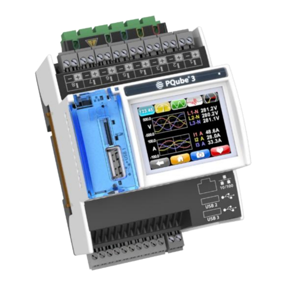
Page 12: Overview Of Pqube 3 Ports, Connections And Controls
PQube 3 Installation Manual Below is an overview of the PQube 3 family and accessories. The left-hand connected modules include the GPS-R, RM8 relay, and CTI 1A/5A modules. The right-hand connected modules include the PM1/PM2 power supplies and UPS 1/2/3 power backup modules. Other accessories include the ATT1/ATT2 attenuators, split core CTs, and ENV2 environmental probes. - Page 13 PQube 3 Installation Manual Coin-cell battery (keeps real time clock 10/100 Ethernet RJ-45 Port. 48V PoE compatible. alive when instrument power is lost) USB-1 High-Speed USB 2.0 Port for USB USB-2 Standard USB 1.0 Port for use ONLY with ENV2 hard drives and adjacent microSD card environmental probes.
-
Page 14: Choosing Modules
1.5 Choosing Modules 1.5.1 Power PQube 3 from 100 to 240 Vac (PM1/PM2) If you have 24 to48 Vdc or 24 Vac, you can use your PQube 3’s internal power supply (just connect the voltage to the power supply screw terminal blocks). -
Page 15: Measure Currents From Secondary Of Current Transformers (Cti-1A/Cti-5A)
PQube 3 Installation Manual 1.5.3 Measure currents from secondary of current transformers (CTI- 1A/CTI-5A) Your PQube 3 comes standard with 8 current channels which are compatible with CTs with 0.333V secondary. But if you need to measure CTs with 1A or 5A secondary wires for your application, use the CTI Current Transformer Input module. -
Page 16: Relay Extension Module For Load Shedding (Rm8)
It also includes an accelerometer to measure shock and vibration, a thermocouple input for wide temperature ranges, and a solar irradiation input. Connect up to 2 probes to your PQube 3 using a MicroUSB to USB cable. You can use a USB cable with a length of up to 15 ft /5 m. -
Page 17: Synchronize Your Pqube 3 Clock To Gps Time
PQube 3 Installation Manual 1.5.7 Synchronize your PQube 3 clock to GPS time Your PQube 3 can synchronize its time clock to GPS, which provides a 1 microsecond internal clock accuracy. This is useful for Class A measurements, or if you need time synchronization for diagnostic and troubleshooting purposes. -
Page 18: Unpacking The Pqube 3
CSA C22.1, CEC, Part I or with both as appropriate. In other countries, follow all local installation requirements and regulations. 2.2.2 Mount your PQube 3 properly and securely Your PQube 3, and its optional modules, are designed to be mounted on an industry standard 35 mm DIN rail as rack- or panel-mounted equipment. Manual#: 851-000135 Version 3.4 –... -
Page 19: Include Overcurrent Protection And A Disconnecting Device
The recommended disconnecting device rating is 600 Vac/dc, Max 30 A, SCCR: 200 kA This device must be clearly marked as the disconnecting device for your PQube 3 and must be marked to indicate the disconnection function. Do not install your PQube 3 in such a way that it becomes difficult to operate this disconnecting device. - Page 20 UL /IEC 61010-1 8.1 and that requires a tool to remove. If you choose to install your PQube 3 in an enclosure, select a UL-listed enclosure that is appropriate for the purpose. If you plan to use an enclosure of this type, you should review its mechanical compatibility with any optional features of your PQube 3 that you plan to use: optional USB connections, optional temperature-humidity probes, etc.
- Page 21 PQube 3 Installation Manual The PQube 3 input circuits are isolated from earth potential. The reference diagram and table below show the respective circuit and isolation rating for each PQube 3 input. Manual#: 851-000135 Version 3.4 – 08/11/2022 Page 21 of 47...
-
Page 22: Connect Pqube 3 To The Power Supply
The PM1 or PM2 module accepts a range of 100 to 240 Vac, 50/60/400 Hz. It plugs into the right side of your PQube 3. This module is ideal for applications where 24 to 48 Vdc, 24 Vac, and PoE are not available. - Page 23 The total combined power output is 5 W, enough to power one additional PQube 3. UPS1 Module Plug the UPS1 module on the right side of your PQube 3 or PM1/PM2 module. This module is always the outermost module on the right side.
-
Page 24: Connecting The Wires
0.5 newton-meters (4.4 inch-pounds) of torque. Observe all voltage ratings and limits. For connections, POWERSIDE recommends wire ferrules for stranded wire, such as Panduit F77 series, for example Panduit F77-6-M. Your PQube 3 meets all IEC requirements for high-... - Page 25 PQube 3 Installation Manual Maximum voltages Connection Measurement Maximum Limitations and remarks Category current PQube 3 terminals 600 Vrms, CAT III L1, L2, L3, N Corresponds to 480V L-N / 830V L-L max for 3-phase, 4-wire Wye/Star systems. Corresponds to 690V L-L max for 3-phase, 3-wire Delta systems.
-
Page 26: Connect Mains Ac Voltage Wires
PQube 3 Installation Manual 2.2.7 Connect Mains AC Voltage Wires The large high-voltage terminal block on the back of your PQube 3 is removable. Refer to the wiring diagrams and use the appropriate wiring scheme for your power configuration. IMPORTANT: Don’t forget to install the Earth conductor. -
Page 27: Installing A Pm1 Or Pm2 Power Supply Module
2.2.9 Installing a PM1 or PM2 Power Supply Module PQube 3 The optional PM1 or PM2 Power Supply Module connects to the right side of your PQube 3; just plug it in. It accepts any 50/60/400 Hz single-phase input between 100 Vac and 240 Vac nominal. Verify that you are connecting the line and neutral wires to the correct terminals on the module. -
Page 28: Installing Split Core Current Transformers (Cts)
Note: You can skip this chapter if you are installing PQube 3v or PQube 3vr (voltage analyzers) Your PQube 3 records AC current by measuring the secondary circuit of a current transformer (CT). When installing current transformers, it is important to match the phases to the voltage inputs and current input (connect the L1 voltage input and the L1 current sensor to the same conductor). - Page 29 POWERSIDE Ultra-Precise CTs are UL listed and utilize a 0.333V secondary output to match your PQube 3’s current input terminals. A burden resistor is built into the CT so you do not need to worry about hazardous open circuit voltages.
- Page 30 Your PQube 3 comes standard with 8 current input channels, which are typically used to measure L1, L2, L3, N, E, plus 3 additional single-phase channels. The current channels on your PQube 3 are rated for 0.333V nominal inputs, and they are designed to be used with CTs with 0.333V secondary.
- Page 31 The CTI module inputs are installed in series with your 1 A or 5 A secondary circuit. The terminal block on your CTI module is connected to the 0.333 V current input channels on your PQube 3. Each CTI module includes 4 current channels, so you can use up to 2 CTI modules per PQube 3.
-
Page 32: Connecting The Env2 Environmental Probes
The RLY1 relay acts as a normally closed switch, which opens upon event detection for at least 3 seconds, or for the duration of the event whatever is longer. The relay trips when the PQube 3 shuts down or restarts. -
Page 33: For Pqube 3R And Pqube 3Vr: Connecting The Output Relays Rly2, Rly3, Rly4
2.2.14 For PQube 3r and PQube 3vr: Connecting the Output relays RLY2, RLY3, RLY4 All PQube 3 have one relay RLY1 described in the section above. However, the PQube 3r and PQube 3vr come with an additional 3 relays: RLY1, RLY2, RLY3. -
Page 34: Wiring Diagrams
PQube 3 Installation Manual 3 Wiring Diagrams 3.1 Wiring diagram for PQube 3v and PQube 3vr PQube 3v, PQube 3vr measures voltage only Manual#: 851-000135 Version 3.4 – 08/11/2022 Page 34 of 47... -
Page 35: Wiring Diagrams (Pqube 3, Pqube 3E, Pqube 3R)
PQube 3 Installation Manual 3.2 Wiring Diagrams (PQube 3, PQube 3e, PQube 3r) 3.2.1 Single Phase L1-N 3.2.2 Single Phase L1-L2 Manual#: 851-000135 Version 3.4 – 08/11/2022 Page 35 of 47... -
Page 36: Single Phase 3-Wire / Split Phase
PQube 3 Installation Manual 3.2.3 Single phase 3-wire / Split Phase 3.2.4 Delta—3 CTs Manual#: 851-000135 Version 3.4 – 08/11/2022 Page 36 of 47... -
Page 37: Delta-2 Cts
PQube 3 Installation Manual 3.2.5 Delta—2 CTs Note: PQube 3 calculates current on remaining channel 3.2.6 Wye/Star Manual#: 851-000135 Version 3.4 – 08/11/2022 Page 37 of 47... -
Page 38: Measuring Neutral Current
PQube 3 Installation Manual 3.2.7 Measuring Neutral Current This applies to any power configuration with Neutral conductor accessible 3.2.8 Measuring Earth Current This applies to any power configuration Manual#: 851-000135 Version 3.4 – 08/11/2022 Page 38 of 47... -
Page 39: Measuring Net Earth Current-Delta
PQube 3 Installation Manual 3.2.9 Measuring Net Earth Current—Delta 3.2.10 Measuring Net Earth Current—Wye/Star Manual#: 851-000135 Version 3.4 – 08/11/2022 Page 39 of 47... -
Page 40: Configuring The Pqube
USB drive or microSD card and insert it directly into your PQube 3. After detecting the new Setup file, your PQube 3 will ask you to reboot so it can load the new settings. -
Page 41: Initial Device Setup
PQube 3 Installation Manual 4.2 Initial Device Setup Your PQube 3 will work right out of the box. Once your PQube 3 has been installed, connected to the monitoring circuit, and powered on, it will begin recording data immediately. The default settings will work for most applications. -
Page 42: Set Current Transformer (Ct) Ratio
PQube 3 Installation Manual 4.2.2 Set Current Transformer (CT) Ratio Note: you can skip this chapter if you are installing a PQube 3v or PQube 3 vr (voltage analyzer). If you are using CTs with 0.333 V secondary To set the CT ratio, simply enter the primary current and secondary voltage into your CT ratio. For example, if you have a current transformer rated at 300 A, with 0.333 V secondary, then you would... - Page 43 The first step of the verification is to make sure that the main LED of the PQube 3 blinks in GREEN. Your PQube 3 will not begin recording until it has locked onto the power configuration. The minimum lock-on voltage is 30 Vac applied between L1 and N, or between L1 and L2.
-
Page 44: Troubleshooting: Common Installation Errors
It is important to correctly connect your CTs (or use the method above to correct a wiring error). Power (watt) calculations are made by multiplying the instantaneous current by the instantaneous voltage. If one or more of your current transformers is incorrectly set up, your PQube 3 will calculate negative power for that phase. - Page 45 You need to have at least 30 Vac applied between the L1 and N terminals or the L1 and L2 terminals. Next, verify that you’ve connected the Earth conductor to your PQube 3. If you forget to install the Earth conductor to your PQube 3, your PQube 3 may have problems locking onto the power configuration.
-
Page 46: Maintenance
UPS1 module before placing them in storage. To fully charge the batteries, turn on your PQube 3 with the UPS1 module plugged in, and let it run for at least 1 day. Manual#: 851-000135 Version 3.4 –... -
Page 47: Cleaning Instructions
If necessary, wipe the accessible parts of your PQube 3 with a slightly damp cloth while it is powered off. Do not use abrasives or chemical cleaners and do not clean your PQube 3 while it is powered on. 5.1.6 Reasons for reset If your PQube 3 is configured to email you whenever system activity occurs, it will notify you whenever it has reset.
Need help?
Do you have a question about the PQube 3 and is the answer not in the manual?
Questions and answers