Table of Contents
Advertisement
Quick Links
Advertisement
Table of Contents

Subscribe to Our Youtube Channel
Related Manuals for em-tec BioProTT FlowTrack SL


Summary of Contents for em-tec BioProTT FlowTrack SL
- Page 1 BioProTT FlowTrack SL User Manual...
- Page 2 GmbH. © Copyright 2022 em-tec GmbH Finning. —All rights reserved. Subject to Technical Changes Owing to our policy of continuous product development, the illustrations and technical data contained in this document may differ slightly from the current version of the device.
-
Page 4: Table Of Contents
10 Flow Measurement with the BioProTT FlowTrack SL ..........30 10.1 Flow Measurement Using the Digital Interface ..........30 10.2 Flow Measurement Using the Analog Interface ..........35 11 Status Information ......................38 Page 4 D101-704 BioProTT FlowTrack SL – User Manual – V 1.0 Copyright em-tec GmbH... - Page 5 13.2 Checking the Current Loops of the BioProTT™ FlowTrack SL....... 41 14 Error Codes and Information ..................44 15 Troubleshooting .......................45 16 Environmental Protection and Disposal ..............51 17 Technical Specifications of the BioProTT FlowTrack SL ........52 Copyright em-tec GmbH D101-704 BioProTT FlowTrack SL – User Manual – V 1.0 Page 5...
- Page 6 The exact software version on your device is displayed on the status information screen and/or can be accessed via the digital interface (see chapter 10.1.3 for more information). Page 6 D101-704 BioProTT FlowTrack SL – User Manual – V 1.0 Copyright em-tec GmbH...
-
Page 7: Intended Purpose And Restrictions
Intended Purpose and Restrictions Intended Purpose The BioProTT™ FlowMeasurement System is designed for the non-invasive measurement of volumetric flow rates of liquids. It is usually used in laboratory and industrial processes within the field of bioprocessing. The device must be used with a compatible em-tec sensor. The measurement is based on the ultrasonic transit time method. Usage Restrictions and Limitations The BioProTT FlowTrack SL was developed and is sold for the above-mentioned intended purpose and use only. -
Page 8: Safety Instructions
• The device should not be covered or exposed to direct heat or sun. • The device must not be opened. Any repairs must be carried out by em-tec GmbH or authorized service personnel only. → Unauthorized opening or repair means the warranty will be void. -
Page 9: Electrical Safety And Electromagnetic Compatibility
61157 2 ed. and IEC 60601-2-37 2 If used as specified in this user manual, the acoustic signals produced by the BioProTT FlowTrack SL and BioProTT Clamp-On SL are, according to current knowledge, harmless for people and the environment. Copyright em-tec GmbH D101-704 BioProTT FlowTrack SL – User Manual – V 1.0 Page 9... -
Page 10: Maintenance And Service
FlowTrack SL and the BioProTT Clamp-On SL may be carried out by em-tec GmbH only. If these instructions are not followed, em-tec GmbH shall accept no liability for the device and the warranty will be void. If you experience any trouble with the measurement despite following the operating instructions, or if your BioProTT FlowTrack SL is damaged in any way, please contact our service department. -
Page 11: General Safety Information, Symbols, Units And Abbreviations
WEEE Directive and national legislation. CE marking: The external power supply unit satisfies the requirements of Low Voltage Directive 2006/92/EC and EMC Directive 2004/108/EC VI Efficiency Mark UK Conformity Assessed European Norms Electrical Certification (22=ID of VDE) Direct current 24V DC from external power supply unit Copyright em-tec GmbH D101-704 BioProTT FlowTrack SL – User Manual – V 1.0 Page 11... -
Page 12: Symbols On Flow Meter, Sensors And On Packaging
Waste devices must be disposed of in accordance with WEEE Directive 2012/19/EU and national legislation. Manufacturer em-tec GmbH · Lerchenberg 20 · 86923 Finning · Germany Serial number Order number The manufacturer declares the conformitiy of the device with the applicable European Regulations and Directives. -
Page 13: Definitions And Abbreviations
BioProTT™ FlowTrack SL Not Applicable Programmable Logic Controller Inner Diameter Outer Diameter Wall Thickness Qmax Maximum flow Received Signal Strength which corresponds to the acoustic coupling Table 4: Definitions and Abbreviations Copyright em-tec GmbH D101-704 BioProTT FlowTrack SL – User Manual – V 1.0 Page 13... -
Page 14: Description Of The Measurement Principle
Consequently, the transit time difference is measured for every pulse. The difference between upstream and downstream measurements is proportional to the volumetric flow rate of the liquid in the tube. Therefore, by accurately measuring the difference between upstream and downstream transit time T and T , we are able down to estimate the flow velocity. Subsequently, the volumetric flow rate is computed from the inner cross section area of the tube and the instrument coefficient. The calculation is carried out by the evaluation device. Page 14 D101-704 BioProTT FlowTrack SL – User Manual – V 1.0 Copyright em-tec GmbH... -
Page 15: Packaging Contents
2x Connecting Cable for "Current Output" – 1 x Connecting Cable for "Digital Output" – Please note: The Accessory Kit must be ordered separately and is not part of the BioProTT FlowTrack SL's scope of supply. Copyright em-tec GmbH D101-704 BioProTT FlowTrack SL – User Manual – V 1.0 Page 15... -
Page 16: Bioprott™ Flowtrack Sl Device Description
(RSS=Received Signal Strength) 16-pin connecting socket for the BioProTT Clamp-On SL BioProTT Clamp-On SL connector with push and pull unlock mechanism. Table 5: Rear Panel Components Page 16 D101-704 BioProTT FlowTrack SL – User Manual – V 1.0 Copyright em-tec GmbH... -
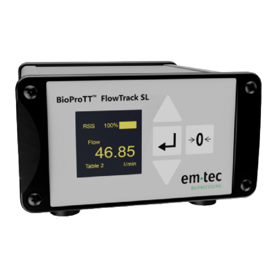
Page 17: Front Panel Of The Bioprott
Only press this button for a short time, otherwise the "sel" mode might remain activated. The zero adjustment button is used • for the zero adjustment of the flow • to reset the totalizer value(s) and exclamation mark. Table 6: Front Panel Components Copyright em-tec GmbH D101-704 BioProTT FlowTrack SL – User Manual – V 1.0 Page 17... -
Page 18: Menu Structure Of The Bioprott
Some screens (e.g. the Flow and Coupling Screen or the Calibration Table Screen) are only visible when a sensor is connected. Figure 4: Menu Structure of the BioProTT FlowTrack SL Page 18 D101-704 BioProTT FlowTrack SL – User Manual – V 1.0 Copyright em-tec GmbH... -
Page 19: Installation And Powering Of The Bioprott
• Plug in the power supply. If needed, connect the 4-20 mA and/or the digital serial output to your data acquisition system. The connectors should be tightened firmly. Unused connector sockets should be covered with the provided flexible grip caps in order to maintain the IP classification. Copyright em-tec GmbH D101-704 BioProTT FlowTrack SL – User Manual – V 1.0 Page 19... - Page 20 + white ground in (GND_in) ground in (GND_in) blue not assigned current loop - black Table 7: Pin Description of the Analog Socket Page 20 D101-704 BioProTT FlowTrack SL – User Manual – V 1.0 Copyright em-tec GmbH...
-
Page 21: Bioprott Tm Clamp-On Sl
Open the spring-loaded lock and swing back the lid. Insert the tube into the channel. Close the BioProTT Clamp-On SL lid and secure it with the help of the spring-loaded lock. Copyright em-tec GmbH D101-704 BioProTT FlowTrack SL – User Manual – V 1.0 Page 21... -
Page 22: Use Of The Bioprott Tm Clamp-On Sl
Ensure that the temperature of the medium is the same as the one the BioProTT Clamp-On SL was adjusted and calibrated for. 4. Ensure that no air bubbles are in the tube during the zero flow adjustment. Allow sufficient time (ca. 5 - 10 minutes) for the system to adapt to ambient conditions, then zero the flow. Only then is the system ready for measurement. Page 22 D101-704 BioProTT FlowTrack SL – User Manual – V 1.0 Copyright em-tec GmbH... - Page 23 While it is possible to carry out measurements outside of the specified flow range, em-tec GmbH cannot guarantee that resulting flow values will be within the given accuracy range. The parameters of the connected BioProTT Clamp-On SL and the selected calibration table are shown on the display of the BioProTT FlowTrack SL under the menu item "Calibration Table" Copyright em-tec GmbH D101-704 BioProTT FlowTrack SL – User Manual – V 1.0 Page 23...
-
Page 24: Disassembly And Storage Of The Bioprott
If any of these parameters change, it is possible to send the sensors in for a re-adjustment. In addition, em-tec GmbH recommends regular calibrations to be carried out. A rule of thumb would be every 24 months. Other than the adjustment, the calibration can be carried out by the customer on site. -
Page 25: General Settings And Functions Of The Bioprott
With the activation of the screen saver, the display brightness is set to the mimimum value of 25 % and the em-tec logo rotates on the screen. It is possible to deactivate the screen saver and return to the screen that was displayed last by using either of the arrow buttons. -
Page 26: Flow Value And Coupling
Table 1. Selecting a different calibration table does not change the calibration factor. Page 26 D101-704 BioProTT FlowTrack SL – User Manual – V 1.0 Copyright em-tec GmbH... -
Page 27: Totalizing
If the coupling is insufficient, or a sensor table has been selected, an exclamation mark appears. This indicates that the displayed totalized volume can differ from the real total flow due to changes in the liquid or the calibration. Table 11: Calibration Table Screen of the BioProTT FlowTrack SL Copyright em-tec GmbH D101-704 BioProTT FlowTrack SL – User Manual – V 1.0 Page 27... - Page 28 If a sensor is disconnected during the totalizer run, the data is deleted. Please note that the totalizer information is not transferred through the RS-232 interface. • Page 28 D101-704 BioProTT FlowTrack SL – User Manual – V 1.0 Copyright em-tec GmbH...
-
Page 29: Setting A Calibration Factor
Table 12: Calibration Factor Screen For more information regarding the calibration factor and how to determine it, read and download our TechNote "Determining the Calibration Factor". Copyright em-tec GmbH D101-704 BioProTT FlowTrack SL – User Manual – V 1.0 Page 29... -
Page 30: Flow Measurement With The Bioprott
Sub-D Connector Wire Color (in supplied cabling) PC_TXD PIN 3 brown PIN 5 blue PC_RXD PIN 2 black Table 13: Pin Description of the Digital Socket Page 30 D101-704 BioProTT FlowTrack SL – User Manual – V 1.0 Copyright em-tec GmbH... - Page 31 – Qmax of the selected calibration table (8 bytes) – <CR> and <LF> – fl ow meter serial number (16 bytes) – blank delimiter – SW-version number (16 bytes) – t he data string is finished by <CR> and <LF> Copyright em-tec GmbH D101-704 BioProTT FlowTrack SL – User Manual – V 1.0 Page 31...
- Page 32 Table 15: Output of digital interface of the BioProTT FlowTrack SL *Note: Beside numerical values, these strings contain the following characters: • "-", a minus symbol is used for negative values or to indicate blanked out values (character hex "0x2D") • "^", indicating overflow condition (character hex: "0x5E") • "v"; indicating underflow condition (character hex: 0x76") Page 32 D101-704 BioProTT FlowTrack SL – User Manual – V 1.0 Copyright em-tec GmbH...
- Page 33 1.00 +41" <CR><LF> ------- ------- ------- "00 1.00 ------- ------- ------- +41" <CR><LF> "00 1.00 +41" <CR><LF> "00 1.00 +41" <CR><LF> "00 1.00 +41" <CR><LF> Copyright em-tec GmbH D101-704 BioProTT FlowTrack SL – User Manual – V 1.0 Page 33...
- Page 34 "59915 V3.0.0.0 "<CR><LF> The sensor information in the first line is blanked. The device information in the second line contains: 59915 = Serial Number of the BioProTT FlowTrack SL V3.0.0.0 = Software Version Page 34 D101-704 BioProTT FlowTrack SL – User Manual – V 1.0 Copyright em-tec GmbH...
-
Page 35: 10.2 Flow Measurement Using The Analog Interface
• 20 mA corresponds to the 1.5 x maximum nominal flow Qmax of the selected calibration table of the connected sensor. → See the table below for the calculation of the specific conversion factors that must be applied. • >20 mA to 23 mA indicate a flow outside the nominal or extended range Copyright em-tec GmbH D101-704 BioProTT FlowTrack SL – User Manual – V 1.0 Page 35... - Page 36 Analog Current Conversion Factor (max. flow range) Flow [ml/min] = (Current Output [mA] - 4 mA) x Calibration Factor Page 36 D101-704 BioProTT FlowTrack SL – User Manual – V 1.0 Copyright em-tec GmbH...
- Page 37 Qmax [ml/min] Analog Current Conversion Factor = (max. Calibration Factor) x Current max [mA] - 4 mA Qmax [ml] = 1.5 x 16 [min x mA] Copyright em-tec GmbH D101-704 BioProTT FlowTrack SL – User Manual – V 1.0 Page 37...
-
Page 38: Status Information
See Troubleshooting. RSS value Table 17: Status Information *Bit value is converted into a hexadecimal value when transmitted with a string over the digital interface. Page 38 D101-704 BioProTT FlowTrack SL – User Manual – V 1.0 Copyright em-tec GmbH... -
Page 39: Cleaning And Disinfection
→ Sterilization processes, especially steam sterilization or autoclaving, may not be used. The following surface disinfectant is recommended: Name Manufacturer Contact Bacillol® AF Hartmann www.hartmann.de Copyright em-tec GmbH D101-704 BioProTT FlowTrack SL – User Manual – V 1.0 Page 39... -
Page 40: Loops For The Bioprott
The pin assignment corresponds to the pins as outlined in the following chapters. Figure 12: BioProTT FlowTrack plus schematics with focus on power supply Page 40 D101-704 BioProTT FlowTrack SL – User Manual – V 1.0 Copyright em-tec GmbH... -
Page 41: Checking The Current Loops Of The Bioprott™ Flowtrack Sl
Figure 14: Schematics —Looking at Pins at the Rear of either the Flow or RSS Socket Tolerances for current measurement (range of amperemeter 0 - 50 mA DC) are as follows: – max. 1 % + 5 digits within range of >50.000 mA – internal resistance <10 Ohm Copyright em-tec GmbH D101-704 BioProTT FlowTrack SL – User Manual – V 1.0 Page 41... - Page 42 Figure 15: Schematics—Looking at Pins at Rear of either the Flow or the RSS socket Tolerances for current measurement (range of amperemeter 0 - 20 mA DC) are as follows: – max. 1% + 5 digits within the range of > 50,000 mA – internal resistance < 10 Ohm Page 42 D101-704 BioProTT FlowTrack SL – User Manual – V 1.0 Copyright em-tec GmbH...
- Page 43 Coupling". Calculating the acoustic coupling RSS by the measured voltage: (Voltage [V] - Zero Point Voltage [V]) RSS [%] = x 100 0.016 x Resistance Copyright em-tec GmbH D101-704 BioProTT FlowTrack SL – User Manual – V 1.0 Page 43...
-
Page 44: Error Codes And Information
Sensor parameter not correct error page w/2B Wrong CRC in burst table error page w/2E Table 20: Error Information on the Different Interfaces Page 44 D101-704 BioProTT FlowTrack SL – User Manual – V 1.0 Copyright em-tec GmbH... -
Page 45: Troubleshooting
SW V3.0 and higher. electromagnetic field or carry the measurement out somewhere else. If the problem persists, please return the sensor and the BioProTT FlowTrack SL for servicing. Copyright em-tec GmbH D101-704 BioProTT FlowTrack SL – User Manual – V 1.0 Page 45... - Page 46 Missing information/values on Display may have frozen. of >50 %. the screen If the problem persists, please return the sensor and the BioProTT FlowTrack SL for servicing. Page 46 D101-704 BioProTT FlowTrack SL – User Manual – V 1.0 Copyright em-tec GmbH...
- Page 47 Check if the correct UART port is used Communication error. and if the settings (e.g. speed, number of bits, etc.) on the computer are the right ones (as described in chapter 10.1.3). Copyright em-tec GmbH D101-704 BioProTT FlowTrack SL – User Manual – V 1.0 Page 47...
- Page 48 If the problem persists, please return the sensor and the BioProTT FlowTrack SL for servicing. Page 48 D101-704 BioProTT FlowTrack SL – User Manual – V 1.0 Copyright em-tec GmbH...
- Page 49 Power the device off. Power the device on again. If the problem persists, please return the sensor and the BioProTT FlowTrack SL for servicing. Copyright em-tec GmbH D101-704 BioProTT FlowTrack SL – User Manual – V 1.0 Page 49...
- Page 50 If the problem persists, please return the sensor and the BioProTT FlowTrack SL for servicing. Table 21: Troubleshooting • The maximum flow range depends on the BioProTT Clamp-On SL. • Please check if the BioProTT Clamp-On SL is suitable for the flow range you need for your application. Page 50 D101-704 BioProTT FlowTrack SL – User Manual – V 1.0 Copyright em-tec GmbH...
-
Page 51: Environmental Protection And Disposal
In accordance with the requirements of EU Directive Waste Electrical and Electronic Equipment (WEEE), our customers in the EU are entitled to return all waste deriving from the products to us – in clean and disinfected condition. The em-tec GmbH WEEE registration DE 99135207 number is: Upon receipt, we repair or dispose of these components properly. -
Page 52: Technical Specifications Of The Bioprott Flowtrack Sl
Transport temperature range -20 °C to 55 °C (-4 °F to 131 ° F) Relative Humidity during transport, storage, 10 % to 96% (non-condensing) and operation Page 52 D101-704 BioProTT FlowTrack SL – User Manual – V 1.0 Copyright em-tec GmbH... - Page 53 Germany, em-tec is part of PSG®, a Dover company. For more information about em-tec, please visit em-tec.de. For more information about PSG®, please visit psgdover.com. About Dover Dover is a diversified global manufacturer and solutions provider with annual revenue of approximately $7 billion.
Need help?
Do you have a question about the BioProTT FlowTrack SL and is the answer not in the manual?
Questions and answers