Table of Contents
Advertisement
Quick Links
Advertisement
Table of Contents
Troubleshooting

Related Manuals for em-tec BioProTT FlowMCP


Summary of Contents for em-tec BioProTT FlowMCP
- Page 1 BioProTT FlowMCP User Manual...
- Page 2 GmbH. © Copyright em-tec GmbH Finning, 2021 Subject to Technical Changes Owing to our policy of continuous product improvement, the illustrations and technical data contained in this document may differ slightly from the current version of the device.
-
Page 4: Table Of Contents
Read Input Register (Function Code: 0x04) ............44 Read Discrete Inputs (Function Code: 0x02) ............ 47 Write Coil (Function Code: 0x05) ................. 47 Read Coil (Function Code: 0x01) ................48 Write Register (Function Code: 0x06) ..............48 Page 4 D214-703 BioProTT™FlowMCP – User Manual – V4.0 Copyright em-tec GmbH... - Page 5 12 Environmental Protection and Disposal ..............72 13 Manufacturer's Declarations ..................73 14 Contact Information for Technical Support .............. 73 15 Technical Specifications of the BioProTT FlowMCP (1-4 channels) ....74 16 Technical Specifications of the BioProTT FlowMCP-a .......... 75 Copyright em-tec GmbH D214-703 BioProTT™FlowMCP - User Manual – V4.0 Page 5...
- Page 6 Received Signal Strength which corresponds to the acoustic coupling ElectroMagnetic Compatibility Not applicable Programmable Logic Controller Inner Diameter Outer Diameter Siemens S7 PLC (Programmable Logic Controller (in German SPS)) Table 1: Abbreviations Page 6 D214-703 BioProTT™FlowMCP – User Manual – V4.0 Copyright em-tec GmbH...
- Page 7 Due to possible failures of the BioProTT FlowMCP or the system it is part of, em-tec GmbH strongly advises against the use of the flow values provided by the BioProTT FlowMCP to directly control the closed loop system unless the risk was fully analyzed and additional risk control measures have been established.
-
Page 8: Intended Purpose And Restrictions
The measurement is based on the ultrasonic transit time method. It is usually used in laboratory, bioprocessing and industrial processes. The device is intended to be mounted and used in a control cabinets only. The device must be used with compatible em-tec BioProTT Clamp-Ons. -
Page 9: Safety Instructions
FlowMCP and the BioProTT Clamp-On may be carried out by em-tec GmbH only. If these instructions are not followed, em-tec GmbH shall accept no liability for the device and the warranty will be void. If you experience any trouble with the measurement despite following the instructions in this document, or if your BioProTT FlowMCP is damaged in any way, please contact our service department. -
Page 10: General Safety Information, Symbols, Units And Abbreviations
Replacement copies of this user manual are available from the manufacturer. Manufacturer em-tec GmbH · Lerchenberg 20 · 86923 Finning · Germany Serial number Order number The manufacturer declares the conformitiy of the device with the applicable European Regulations and Directives. -
Page 11: Description Of The Measurement Principle
Therefore, by accurately measuring the difference between upstream and downstream transit time T and T , it is down possible to determine the flow velocity. Copyright em-tec GmbH D214-703 BioProTT™FlowMCP - User Manual – V4.0 Page 11... -
Page 12: Packaging Contents
Extension cables (ID 13065) for the BioProTT Clamp-On, one for every supported flow channel. The cables are 1.1 m long and intended to be used in a process control cabinet. Page 12 D214-703 BioProTT™FlowMCP – User Manual – V4.0 Copyright em-tec GmbH... - Page 13 Clamp-On, one for every supported flow channel. The cables are 1.1 m long and intended to be used in a process control cabinet. One (1) analog connector (ID 13399); connected to the device Copyright em-tec GmbH D214-703 BioProTT™FlowMCP - User Manual – V4.0 Page 13...
-
Page 14: Installation Of The Bioprott™ Flowmeasurement System
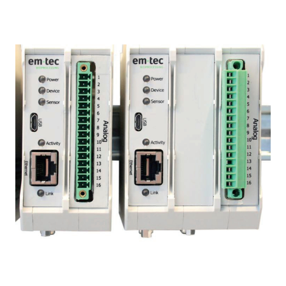
D-Sub connection socket to connect the sensor to the extension cable #1-#4 Ethernet connection connector for Ethernet / LAN cable (Modbus TCP) USB connection USB for em-tec service purposes only Page 14 D214-703 BioProTT™FlowMCP – User Manual – V4.0 Copyright em-tec GmbH... - Page 15 The PIN assignment on the power connection is as follows: PIN Number Meaning +24 V DC, max. 2A 1 2 3 4 Ground Figure 3: Terminal block Table 4-2: Pin assignment terminal block Copyright em-tec GmbH D214-703 BioProTT™FlowMCP - User Manual – V4.0 Page 15...
-
Page 16: Device Description: Bioprott™ Flowmcp-A (1 Or 2 Channels)
D-Sub connection socket to connect the sensor to the extension cable #1-#2 Ethernet connection connector for Ethernet / LAN cable (Modbus TCP) USB connection USB for em-tec service purposes only LEDs LEDs for device status signalization Lights: when power is connected Off: when no power is connected;... - Page 17 1 2 3 4 Ground Figure 5: Terminal Block Table 5-2: Pin assignment terminal block The maximum resistance load on a current output must not exceed 560 Ω. Copyright em-tec GmbH D214-703 BioProTT™FlowMCP - User Manual – V4.0 Page 17...
-
Page 18: Installation Of The Bioprott
Then disconnect and remove the sensor extension cables and the Ethernet connection and/or analog connection. • Last, pull the DINrail fixing bracket downwards e.g. by using a screwdriver. Figure 7: Disassembly Page 18 D214-703 BioProTT™FlowMCP – User Manual – V4.0 Copyright em-tec GmbH... -
Page 19: Powering Of Bioprott™ Flowmcp
Clamp-On, be sure not to impair the function of the tubing system. • Ensure that the tube size which is used corresponds with the size of the BioProTT Clamp-On. Copyright em-tec GmbH D214-703 BioProTT™FlowMCP - User Manual – V4.0 Page 19... -
Page 20: Mounting And Installation Of The Bioprott
It is recommended that only one extension cable is used when connecting a BioProTT Clamp-On. • The total length of cable between sensor and flow meter must not exceed 4 m. Figure 10: Cable Length and Connection Page 20 D214-703 BioProTT™FlowMCP – User Manual – V4.0 Copyright em-tec GmbH... -
Page 21: Line Routing, Shield And Measures To Combat Interference Voltage
80 %. Avoid lines with foil shields since the foil can be damaged very easily as result of tensile and compressive stress on attachment. The consequence is a reduction in the shielding effect. Copyright em-tec GmbH D214-703 BioProTT™FlowMCP - User Manual – V4.0... - Page 22 Continue the shield as far as the module, but do not connect it again at this point! Make sure that the grounding of your system complies with installation standards. Page 22 D214-703 BioProTT™FlowMCP – User Manual – V4.0 Copyright em-tec GmbH...
-
Page 23: Attaching The Bioprott
Ideally, the tube should be straight for a distance of 15 x the ID of the tube on either side of the sensor. Figure 12: Distance on either side of the sensor Copyright em-tec GmbH D214-703 BioProTT™FlowMCP - User Manual – V4.0 Page 23... -
Page 24: Clamp-On
GmbH cannot guarantee that resulting flow values will be within the given accuracy range. The parameters of the connected BioProTT Clamp-On and the selected calibration table are displayed in the sensor information page of the web interface of the BioProTT FlowMCP. -
Page 25: Clamp-On
Clamp-On is not suited for cleaning processes using machines. Sterilization processes, especially steam sterilization or autoclaving, may not be used. The following surface disinfectant is recommended: Name Manufacturer Contact Bacillol® AF Hartmann www.hartmann.de Copyright em-tec GmbH D214-703 BioProTT™FlowMCP - User Manual – V4.0 Page 25... -
Page 26: Tm Flowmcp
Connect a 24V DC power supply to the power connector as described in chapter 5.4. Connect the em-tec sensors by using the extension cables as described in chapter 5.6. Connect an Ethernet cable to the Ethernet socket to PC for configuration. -
Page 27: Flowmcp
• It can take some time for the web interface to fully load. Please note: It is the responsibility of the user to ensure IT security. em-tec GmbH is not • responsible for any errors or inconsistencies in the measurement that result from a lack of security. - Page 28 Page 28 D214-703 BioProTT™FlowMCP – User Manual – V4.0 Copyright em-tec GmbH...
- Page 29 Possibility to open the device logging page. For more information, refer to the description below. Software version of the BioProTT FlowMCP Link to the em-tec website Table 7: Description of the main page of the web interface for the BioProTT FlowMCP (1-4 channels) Copyright em-tec GmbH D214-703 BioProTT™FlowMCP - User Manual –...
-
Page 30: Flowmcp-A
• "green" indicating a sensor is connected • "gray" indicating no sensor is connected Flow value [ml/min] of the flow channel RSS value [%] of the flow channel Page 30 D214-703 BioProTT™FlowMCP – User Manual – V4.0 Copyright em-tec GmbH... - Page 31 Copyright em-tec GmbH D214-703 BioProTT™FlowMCP - User Manual – V4.0 Page 31...
- Page 32 Error of the analog interface (displayed as hexadecimal value). For more information, refer to chapter 10 "Troubleshooting". Status information of the analog interface (displayed as hexadecimal value). For more information, please contact em-tec GmbH. Software version of the analog interface Possibility to open the set-up page.
-
Page 33: Tm Flowmcp
For more information regarding the calibration factor as such and how to determine it, please contact em-tec GmbH and ask for our Application Note about this subject. em-tec ID of the connected sensor Serial number of the connected sensor... -
Page 34: Flowmcp
(Please note: like "unknown" but without the “n”). Figure 16: Set-Up Page Log-In 6.4.1 Set-Up Page for the BioProTT FlowMCP (1-4 channels) Figure 17: Set-Up page for the BioProTT FlowMCP (1-4 channels) Page 34 D214-703 BioProTT™FlowMCP – User Manual – V4.0 Copyright em-tec GmbH... - Page 35 Copyright em-tec GmbH D214-703 BioProTT™FlowMCP - User Manual – V4.0 Page 35...
- Page 36 This field is selected as default. When selected, the RSS value over Modbus TCP and in the web interface is clipped to 100 %. When not selected, values up to 133 % are possible. Page 36 D214-703 BioProTT™FlowMCP – User Manual – V4.0 Copyright em-tec GmbH...
- Page 37 For more information regarding the calibration factor as such and how to determine it, please contact em-tec GmbH and ask for our Application Note about this subject. *Store button Clicking this button saves all performed changes on the set-up page.
- Page 38 BioProTT™ FlowMCP 6.4.2 Set-Up Page for the BioProTT FlowMCP-a Figure 18: Set-Up page of the BioProTT FlowMCP-a Page 38 D214-703 BioProTT™FlowMCP – User Manual – V4.0 Copyright em-tec GmbH...
- Page 39 Copyright em-tec GmbH D214-703 BioProTT™FlowMCP - User Manual – V4.0 Page 39...
- Page 40 Please note: This setting only affects the RSS value given out through the Modbus-TCP interface; the RSS value over the analog interface is not affected by this setting Page 40 D214-703 BioProTT™FlowMCP – User Manual – V4.0 Copyright em-tec GmbH...
- Page 41 For more information regarding the calibration factor as such and how to determine it, please contact em-tec GmbH and ask for our Application Note about this subject. Possibility to disable the analog interface. After every device start, the analog interface is enabled. Only when the device is in running mode, can the analog interface be disabled.
- Page 42 Before clicking reset, check the error according to the information given in chapter 10 "Troubleshooting". Table 11: Description of the set-up page of the BioProTT FlowMCP-a Page 42 D214-703 BioProTT™FlowMCP – User Manual – V4.0 Copyright em-tec GmbH...
-
Page 43: Flowmcp
For every hour the device is running, a new log file will be created as long as a logging was present. The log files are important for the service department of em-tec GmbH. If you contact our service department and are asked for the log files, the files can be downloaded by clicking on the relevant files. -
Page 44: Modbus Interface
1 Flow Channel 2 REG_RSS, See channel 1 REG_FLOW_SLOW_HI, REG_FLOW_SLOW_LO, REG_FLOW_FAST_HI, REG_FLOW_FAST_LO, REG_ERROR, REG_R_TABLE, Flow Channel 3 REG_RSS, See channel 1 REG_FLOW_SLOW_HI, REG_FLOW_SLOW_LO, REG_FLOW_FAST_HI, REG_FLOW_FAST_LO, REG_ERROR, REG_R_TABLE, Page 44 D214-703 BioProTT™FlowMCP – User Manual – V4.0 Copyright em-tec GmbH... - Page 45 High 16 bit word of sensor max flow REG_SENS_MAX_FLOW_HI -999999...+999999 (the actual (Qmax), channel 1 Qmax depends on the High 16 bit word of sensor max flow connected sensor) REG_SENS_MAX_FLOW_LO (Qmax), channel 1 Copyright em-tec GmbH D214-703 BioProTT™FlowMCP - User Manual – V4.0 Page 45...
- Page 46 High 16 bit word of sensor serial REG_SENS_SERIAL_HI number channel 4 See above Low 16 bit word of sensor serial REG_SENS_SERIAL_LO number channel 4 Table 14: Additional Information Page 46 D214-703 BioProTT™FlowMCP – User Manual – V4.0 Copyright em-tec GmbH...
-
Page 47: Read Discrete Inputs (Function Code: 0X02)
Before doing so, check the device in regard to the reported error listed in the troubleshooting. REG_W_RESET Reset channel 2 REG_W_RESET Reset channel 3 REG_W_RESET Reset channel 4 Copyright em-tec GmbH D214-703 BioProTT™FlowMCP - User Manual – V4.0 Page 47... -
Page 48: Read Coil (Function Code: 0X01)
(0 REG_RSS, 1 REG_FLOW_SLOW_HI, 2 REG_FLOW_SLOW_LO, 3 REG_FLOW_FAST_HI, 4 REG_FLOW_FAST_LO, 5 REG_ERROR, 6 REG_R_TABLE) Flow channel 2: (7 REG_RSS, 8 REG_FLOW_SLOW_HI, 9 REG_FLOW_SLOW_LO, 10 REG_FLOW_FAST_HI, 11 REG_FLOW_FAST_LO, 12 REG_ERROR, 13 REG_R_TABLE) … and so on. Page 48 D214-703 BioProTT™FlowMCP – User Manual – V4.0 Copyright em-tec GmbH... -
Page 49: Analog Interface
4 mA equals 0 % RSS/coupling (no signal) • 20 mA equals 100 % RSS (or 133 %, depending on the setting). Figure 20: Flow chart RSS on analog output Copyright em-tec GmbH D214-703 BioProTT™FlowMCP - User Manual – V4.0 Page 49... -
Page 50: Tm Flowmcp-A
It is possible to store the settings for "flow value at 4 mA" and "flow value at 20 mA" for a total of 16 different sensors on the BioProTT FlowMCP. Page 50 D214-703 BioProTT™FlowMCP – User Manual – V4.0 Copyright em-tec GmbH... - Page 51 Q at 20 mA - (5 * Q at 4 mA) Flow Q= set calibration factor 16 mA 4 mA The maximum external resistance load must not exceed 560 Ω. Copyright em-tec GmbH D214-703 BioProTT™FlowMCP - User Manual – V4.0 Page 51...
-
Page 52: Zero Flow Adjustment Via The Analog Interface
Once the button was pressed, the falling current will have no effect. – You need one push button per flow channel. The push button must not remain pressed but go back to its – original position. Page 52 D214-703 BioProTT™FlowMCP – User Manual – V4.0 Copyright em-tec GmbH... -
Page 53: Cleaning The Bioprott
To dampen the cloth, use water only. Make sure that no particles or water enter the device. The accessory connecting plugs and power connection must only be plugged in when dry. Copyright em-tec GmbH D214-703 BioProTT™FlowMCP - User Manual – V4.0 Page 53... -
Page 54: Troubleshooting, Support And Service
If any issues occur with the BioProTT™ FlowMCP, try the following suggestions. If the problem persists, please contact your local distributor or em-tec GmbH directly. The most common reason for an error/warning occurring is that the system has not been properly assembled. - Page 55 FlowMCP resets the board to clear the error. → If the error is no longer present, then the device can be used like normal. → If the problem persists, return the device for servicing. Copyright em-tec GmbH D214-703 BioProTT™FlowMCP - User Manual – V4.0 Page 55...
- Page 56 Power on the device again (reconnect the power supply). too high. → If the error is no longer present, the device can be used like normal. → If the problem persists, return the device for servicing. Page 56 D214-703 BioProTT™FlowMCP – User Manual – V4.0 Copyright em-tec GmbH...
- Page 57 → If the error is no longer present, the device can be used like BioProTT FlowMCP. normal. → If the problem persists, return the device for servicing. Copyright em-tec GmbH D214-703 BioProTT™FlowMCP - User Manual – V4.0 Page 57...
- Page 58 → If the error is no longer present, the device can be used like normal. → If the problem persists, return the device for servicing. Page 58 D214-703 BioProTT™FlowMCP – User Manual – V4.0 Copyright em-tec GmbH...
- Page 59 FlowMCP resets the board to clear the error. → If the error is no longer present, then the device can be used like normal. → If the problem persists, return the device for servicing. Copyright em-tec GmbH D214-703 BioProTT™FlowMCP - User Manual – V4.0 Page 59...
- Page 60 (and therefore to the internal database) → If the error is no longer present, the device can be used like failed. normal. → If the problem persists, return the device for servicing. Page 60 D214-703 BioProTT™FlowMCP – User Manual – V4.0 Copyright em-tec GmbH...
- Page 61 If the error is no longer present, the device can be used like board is defect or permanently reset. normal. → If the problem persists, return the device for servicing. Copyright em-tec GmbH D214-703 BioProTT™FlowMCP - User Manual – V4.0 Page 61...
- Page 62 During an automatic reset of the board, the measured flow value and/or the RSS value of the respective flow channels may go down to zero for a few seconds. Table 20: Global Errors and Warnings Page 62 D214-703 BioProTT™FlowMCP – User Manual – V4.0 Copyright em-tec GmbH...
- Page 63 FlowMCP resets the board to clear the error. → If the error is no longer present, then the device can be used like normal. → If the problem persists, return the device for servicing. Copyright em-tec GmbH D214-703 BioProTT™FlowMCP - User Manual – V4.0 Page 63...
- Page 64 FlowMCP resets the board to clear the error. → If the error is no longer present, then the device can be used like normal. → If the problem persists, return the device for servicing. Page 64 D214-703 BioProTT™FlowMCP – User Manual – V4.0 Copyright em-tec GmbH...
- Page 65 FlowMCP resets the board to clear the error. → If the error is no longer present, then the device can be used like normal. → If the problem persists, return the device for servicing. Copyright em-tec GmbH D214-703 BioProTT™FlowMCP - User Manual – V4.0 Page 65...
- Page 66 FlowMCP resets the board to clear the error. → If the error is no longer present, then the device can be used like normal. → If the problem persists, return the device for servicing. Page 66 D214-703 BioProTT™FlowMCP – User Manual – V4.0 Copyright em-tec GmbH...
- Page 67 During an automatic reset of the board, the measured flow value and/or the RSS value of the respective flow channels may go down to zero for a few seconds. Table 21: Analog Errors and Warnings Copyright em-tec GmbH D214-703 BioProTT™FlowMCP - User Manual – V4.0 Page 67...
- Page 68 Check if the IP address of the MCP device is correct and is in the same network as the PLC. Disconnect the Ethernet interface. Reconnect the Ethernet interface again. If the problem persists, return the device for servicing. Page 68 D214-703 BioProTT™FlowMCP – User Manual – V4.0 Copyright em-tec GmbH...
- Page 69 Check if the sensor is damaged in any way. Flow offset is bigger than 3,000 ml/min. If the flow offset remains despite the pump being stopped, please contact em-tec GmbH. Analog output value not within the expected range Check if any error is present on the device.
-
Page 70: 10.2 Status Information Troubleshooting
Modbus TCP interface as hexadecimal value in form of a 16 bit word (2 byte). When the status information is used for the integration of the BioProTT FlowMCP into an industrial system, please contact em-tec GmbH for more detailed information in regard to the integration. The status information looks as follows:... - Page 71 Sensor war zeroed or sensor is known and was zeroed sensor is possible, calibration before table 1 of sensor is set Bit 0 of currently used calibration table (table 1 selected) Copyright em-tec GmbH D214-703 BioProTT™FlowMCP - User Manual – V4.0 Page 71...
-
Page 72: Electrical Safety And Electromagnetic Compatibility
Electronic Equipment (WEEE), our customers in the EU are entitled to return to us all waste devices – in clean and disinfected condition. The em-tec GmbH WEEE registration number is "DE 99135207 ". Upon receipt, we repair or dispose these devices properly. -
Page 73: Manufacturer's Declarations
The product marked with the CE sign fulfills the European harmonized standards of electromagnetic and electrical safety requirements for industrial devices. The declaration of conformity and other certificates are provided at: em-tec GmbH, Lerchenberg 20, 86923 Finning, Germany Contact Information for Technical Support Returns/RMA... -
Page 74: 15 Technical Specifications Of The Bioprott Tm Flowmcp (1-4 Channels)
10 % to 96 % (non-condensing) EMC: The device was tested according to EN/IEC 61326-1, however, the safety safety of the overall system must be ensured by the customer. Page 74 D214-703 BioProTT™FlowMCP – User Manual – V4.0 Copyright em-tec GmbH... -
Page 75: Technical Specifications Of The Bioprott
10 % to 96 % (non-condensing) EMC: The device was tested according to EN/IEC 61326-1, however, the safety safety of the overall system must be ensured by the customer. Copyright em-tec GmbH D214-703 BioProTT™FlowMCP - User Manual – V4.0 Page 75... - Page 79 About em-tec GmbH em-tec has been a specialist for flow measurement systems in the medical and bioprocessing technology sector for over 30 years. The company's core competence is the non-invasive flow measurement using the ultrasonic transit-time method, that is used for applications in extracorporeal circulation systems of life- sustaining systems as well as in biopharma applications that use flexible tubes.
Need help?
Do you have a question about the BioProTT FlowMCP and is the answer not in the manual?
Questions and answers