Table of Contents
Advertisement
Operating Instructions
TM
BioProTT
Flow Measurement System
© em-tec GmbH
All rights reserved, especially with respect to reproduction, distribution and translation. These
Operating Instructions or any part thereof must not be reproduced, saved, processed, duplicated or
distributed without the written consent of em-tec GmbH.
TM
BioProTT
Flow Measurement System
Version 1.00
page 1 of 75
Advertisement
Table of Contents
Troubleshooting

Related Manuals for em-tec BioProTT


Summary of Contents for em-tec BioProTT
- Page 1 © em-tec GmbH All rights reserved, especially with respect to reproduction, distribution and translation. These Operating Instructions or any part thereof must not be reproduced, saved, processed, duplicated or distributed without the written consent of em-tec GmbH. BioProTT Flow Measurement System Version 1.00...
- Page 2 Brief Operating Instructions - Quick Guide BioProTT™ Flow Measurement System Safety instructions Chapter 2 - Page 6 ff. Familiarize yourself with the safety instructions! Chapter 6 - Page 15 ff. Setting up and connecting the flow meter Connect the BioProTT™ flow meter to power supply, e.g.
-
Page 3: Table Of Contents
BioProTT™ FlowTrack DINrail ..................... 35 7.7.1.1 Received Signal Strength (RSS / Acoustic Coupling) ..............35 7.7.1.2 Flow Value ............................ 36 Measurement Using the Digital Interface (RS232) of the Different BioProTT™ Flow Meters 7.7.2 Measurements Using BioProTT™ FlowTrack plus ..............41 7.7.3 7.7.3.1 Flow Value and Coupling ...................... - Page 4 ................. 67 NFORMATION ON COUSTIC UTPUT 13.2 ....................69 ECLARATION OF ONFORMITY ORDERING INFORMATION FOR THE BIOPROTT FLOW MEASUREMENT SYSTEM AND ACCESSORIES ........................... 70 RETURN INFORMATION AND DECLARATION OF CONTAMINATION ......72 APPENDIX ............................74 TT™ C 16.1 ........74...
- Page 5 You should therefore carefully read the Operating Instructions before use. These instructions contain important information on the safe handling of the BioProTT flow measurement system and accessories. Read these Operating Instructions carefully before using the device and accessories, and keep them in an easily accessible location.
-
Page 6: Intended Use
If this device is not used as intended, the user may be exposed to risks that were not taken into account during development. The BioProTT flow measurement system is designed for non-invasive measurement of volumetric flow of liquids. The measurement is based on the ultrasonic transit time method. - Page 7 Stop using the device and send it to our back for inspection; see chapter RETURNS / RMA. Malfunctions, The BioProTT flow measurement system may be influenced by inaccurate radio frequency (RF) devices. This includes mobile RF measured value communication equipment.
-
Page 8: General Important Information
The DC power supply line shall be shorter than 30 m and shall not leave the building. Damage due to At all device settings of the BioProTT flow measurement system ultrasonic sound the Clamp-On Transducer generates ultrasonic sound only at a low acoustic output level. -
Page 9: Symbols, Units And Abbreviations
CE marking: The external power supply unit satisfies the requirements of Low Voltage Directive 2006/92 EC and EMC Directive 2004/108 UL test mark for recognized components for Canada and the USA by Underwriter Laboratories Inc. BioProTT Flow Measurement System Version 1.00 page 9 of 75... -
Page 10: Symbols On Flow Meter, Sensors And On Packaging
IP20 Protected against access by finger (BioProTT™ FlowTrack DINrail) Direct current (24 V DC from external power supply unit) Do not dispose of this device as domestic waste! Waste devices must be disposed of in accordance with Directive 2002/96/EEC and national legislation. - Page 11 Caution, fragile! Handle with care! Protect against moisture! Store in a dry place. Temperature limit during storage Moisture limit during storage (non-condensing) non- condensing Air pressure limit Storage Transport BioProTT Flow Measurement System Version 1.00 page 11 of 75...
-
Page 12: Units
Outer diameter = internal diameter ID + 2 x wall thickness WT 3.5 Definitions and Abbreviations Definitions, Meaning Abbreviation CT / BCT Clamp-On Transducer respectively BioProTT Clamp-On Transducer BioProTT™ FlowTrack, BioProTT FlowTrack plus, flow meter BioProTT FlowTrack DINrail flow sensor BioProTT Clamp-On Transducer... -
Page 13: Description Of Measuring Principle
4 Description of Measuring Principle The physical measurement principles applied in the BioProTT flow measurement system are described in this chapter. The BioProTT flow measurement system uses the ultrasonic transit-time method (TT = transit-time) which delivers precise flow values in tube systems and pipes. -
Page 14: Packaging Contents
BioProTT™ FlowTrack (without display), or o BioProTT™ FlowTrack plus (with display) o BioProTT™ FlowTrack DINrail (without display for DIN rail mounting) Please note: Flexible grip caps are provided for all sockets and should not be removed until a socket is actually used to avoid any dirt accumulation or any potential short circuits. - Page 15 Please download current driver from link specified on actual adapter labeling. Terminal block adapter - BioProTT™ FlowTrack DINrail only Extension cable for flow sensor in process control cabinet - BioProTT™ FlowTrack DINrail only Please note: a picture is not yet available ...
-
Page 16: Initial Set Up
(or 4-wire) devices are providing power i.e. there is a separate power supply for the device and the loop. The BioProTT™ flow measurement system supports both modes of operation. However, the flow meter always needs power to operate! In a 2 wire environment with the DC power supply located e.g. - Page 17 Below pin assignments and cable colors for round connectors for Power, Flow and RSS sockets are shown (identical for all flow meter variants). Figure 3: BioProTT flow meter rear view with one analogue plug connected -example w/ Flow socket Figure 4: BioProTT view of power and analogue Flow and RSS socket...
-
Page 18: Wiring In "Active" Set-Up When Flow Meter Is Not Relying On Current Loop Power
The “active” set-up means that the power supply used to power the flow meter is also used to power the current loop. To do so, a wire bridge is applied from Pin 1 to Pin 2 of the Flow respective RSS cable. BioProTT Flow Measurement System Version 1.00... - Page 19 For details see the circuit diagram below and observe the wiring instructions. Figure 5: BioProTT flow meter rear view with one analogue plug connected -example w/ flow socket Pin No Flow / RSS Wire color Connected with (in supplied cabling)
-
Page 20: Wiring In "Passive" Set-Up When Powering Flow Meter Via Current Loop
This is explained in detail below. Figure 7: BioProTT flow meter rear view with one analogue plug connected -example w/ RSS socket Pin No Flow / RSS... -
Page 21: Installation And Operation Of Bioprott™ Flowtrack
6.2 Installation and Operation of BioProTT™ FlowTrack Compliance with the prescribed operating parameters and safety information must be ensured prior to putting into service. The following installation instructions must be strictly observed. The BioProTT FlowTrack can be used as bench top flow meter or mounted with screws on surfaces. -
Page 22: Rear Panel Bioprott™ Flowtrack
6.2.2 Rear Panel BioProTT™ FlowTrack Figure 10: Rear view of BioProTT FlowTrack Components Description On/Off button Push the button to power the device on or off. Note: this button is only relevant when power is supplied via the power socket. The button does not affect power supplied via either Flow or RSS socket. -
Page 23: Pin Assignment And Cable Colors For Round Connector For Digital Interface
AND 4-20 MA CIRCUITS for details. Sourcing information for plugs: The 768/718 series from Binder is used for the connections of the BioProTT™ flow meter. The circular plug design optimally supports the flow measurement application. Please note: unused connector sockets should be covered with the provided flexible grip caps. -
Page 24: Connecting And Powering Up The System
NOT originally shipped. The BioProTT™ flow meter shall be powered by 24 V DC (±10%). The power supply shall deliver at least 300 mA. Please note: the flow meter can be powered with the provided power supply or with another external power supply meeting the above mentioned specifications. -
Page 25: Information
Switching power on or via process control A green LED on the BioProTT FlowTrack indicates that it is ready to use after it has been powered-on: Figure 11: Front and rear view of BioProTT FlowTrack DINrail BioProTT Flow Measurement System Version 1.00... -
Page 26: Installation And Operation Of Bioprott™ Flowtrack Plus
BioProTT FlowTrack DINrail are identical with BioProTT FlowTrack. 6.4 Installation and Operation of BioProTT™ FlowTrack plus Compliance with the prescribed operating parameters and safety information must be ensured prior to set up. The following installation instructions must be strictly observed. -
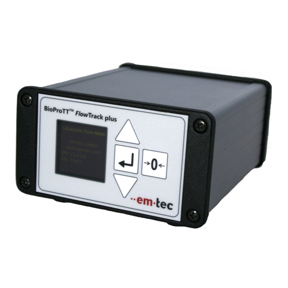
Page 27: Front Panel Bioprott™ Flowtrack Plus
The flow meter takes about 15s to initialize after power on. The device is ready to operate, once the “flow” screen appears. Please note: the display will be updated every second. Figure 12: Front view of BioProTT FlowTrack plus Basic operation of the device: Button... -
Page 28: Menu Structure Of Bioprott™ Flowtrack Plus
6.4.2 Menu Structure of BioProTT™ FlowTrack plus Flow chart of menu structure: Initializing Device Note: The message “initializing device” only appears after switching on the device Measure Flow Start/Stop Totalizing Set Calibration Table Set Calibration Factor Adjust Brightness Display Status Information... -
Page 29: Rear Panel Bioprott™ Flowtrack Plus
6.4.3 Rear Panel BioProTT™ FlowTrack plus The rear panel of BioProTT™ FlowTrack plus is identical to the flow meter without display, i.e. BioProTT™ FlowTrack. Please see chapter REAR PANEL BIOPROTT™ FLOWTRACK. 6.4.4 Connecting and Powering up The flow meter is operated with the provided power supply. -
Page 30: Mounting
6.5 Mounting BioProTT flow meters with standard industry housing are designed as table top devices which can be stacked, e.g. like a pump tower. It is also possible to fix the flow meter with screws using the threaded sleeve of each of the foot pieces. -
Page 31: Tm Clamp-On Transducers
The prescribed parameters are listed in the data sheets supplied with the transducer. 7.2 Clamping Onto Tube The 16-pin circular connector of the BioProTT Clamp-On Transducer is connected to the rear of the BioProTT flow meter (see View of Front and Rear). -
Page 32: Measurement Accuracy And Tube Arrangement
Ensure a straight lead-in and run-on area (“straight inlet”): To prevent turbulence and the associated measurement inaccuracies, it is recommended to stretch the tube out straight in the area where it is clamped. BioProTT Flow Measurement System Version 1.00 page 32 of 75... -
Page 33: Received Signal Strength (Rss / Acoustic Coupling)
This is especially important when soft tubing (like e.g.silicone) with a low wall thickness is used. Fitting this tubing into the measurement channel might lead to concave folding of the tubing wall and a misalignment (low BioProTT Flow Measurement System Version 1.00... - Page 34 A couplant ensures an easy slip of the tube in the channel and provides repeatable alignment of the tubing wall. To ensure an optimal measurement em-tec will provide support about the usage of couplant for your specific tubing- sensor system.
-
Page 35: Zero Adjustment
(see chapter CUSTOM CALIBRATION PROCEDURE). 7.7 Performing Flow Measurements 7.7.1 Measurement Using the Analog Interface of BioProTT™ FlowTrack, BioProTT™ FlowTrack plus and BioProTT™ FlowTrack DINrail The flow meter can be connected to data acquisition or process control systems with the analogue interface. -
Page 36: Flow Value
Diagram 1: Flow rate versus output current To calculate an output current into the flow value (with adjusted calibration factor accounted for), use the following equation: Flow[ml/min]= (Current [mA]-4[mA])*Conversion Factor (max flow range) BioProTT Flow Measurement System Version 1.00 page 36 of 75... - Page 37 Please note: the conversion factor is a fixed value based on the maximum flow range of a sensor when the calibration factor is set to 1.50. It is not dependant on the actual chosen calibration factor. BioProTT Flow Measurement System Version 1.00...
-
Page 38: Measurement Using The Digital Interface (Rs232) Of The Different Bioprott™ Flow Meters
7.7.2 Measurement Using the Digital Interface (RS232) of the Different BioProTT™ Flow Meters Via the asynchronous serial communication port the different BioProTT flow meters can communicate with a host system. The interface must be initialized to the following parameters: Baud rate 38400 Baud ... - Page 39 °C (38 := 38 °C) <cr> 0x0d Carriage Return <lf> 0x0a Linefeed Please note: if your own applications are programmed, both error- and statusbyte must be evaluated for a proper system assessment. BioProTT Flow Measurement System Version 1.00 page 39 of 75...
- Page 40 Flow range of calibration Sensor disconnected “00 E2 --- ---- ------ ------ ------ +42” Sensor disconnected, request for status information “------------------------------- -------- -------- ------ -- ------ ------ 61414 FT_GFX_EV2200” BioProTT Flow Measurement System Version 1.00 page 40 of 75...
-
Page 41: Measurements Using Bioprott™ Flowtrack Plus
7.7.3 Measurements Using BioProTT™ FlowTrack plus BioProTT™ FlowTrack plus is equipped with a display and supports the following functions via the graphical user interface (GUI). The screens shown are only examples of actual possible screen contents. When using the display and changing settings like calibration table or... -
Page 42: Selection Of Calibration Factor
Changing the calibration factor will instantly effect the flow Flow: 0.500 value displayed on the screen and also on the analogue and l/min digital output. The calibration factor alters the flow by the following equation: BioProTT Flow Measurement System Version 1.00 page 42 of 75... -
Page 43: Adjustment Of Brightness
(1) liter. When the value is equal or higher than one (1) liter the unit is changed to [l]. In this case the maximum displayed total flow is 999.99 liter whereas the digits for ml shall be two. When the sum exceeds a value of 999.99 liters the lower left corner BioProTT Flow Measurement System Version 1.00... - Page 44 Totalizing Time is stopped and the Total Flow value is not be modified (no further summation). If any sensor is (re)connected the totalizer is reset and the exclamation mark is removed. BioProTT Flow Measurement System Version 1.00...
-
Page 45: Status And Error Information
(see chapter MEASUREMENT USING THE DIGITAL INTERFACE (RS232) OF THE DIFFERENT BIOPROTT™ FLOW METERS) via the serial interface. Additionally the factor can be set via the display for the BioProTT FlowTrack plus (see chapter SELECTION OF CALIBRATION FACTOR) BioProTT Flow Measurement System Version 1.00... - Page 46 This can be checked with a reference device or timed collection. BioProTT Flow Measurement System Version 1.00 page 46 of 75...
-
Page 47: Status Information, Troubleshooting, Support And Service
8 Status Information, Troubleshooting, Support and Service Available Status Codes/Information for Flow Meter The following status information is provided via the different interfaces: Description Digital Analogue Analogue Display (BioProTT Interface Interface Interface RS 232 Status 4-20mA Flow 4-20mA RSS FlowTrack plus Byte “ss”... -
Page 48: Available Error Codes/Information For Flow Meter
Please see also the chapter TROUBLESHOOTING. The following error information is provided via the different interfaces: Description Digital Analogue Analogue Display Interface Interface Interface (BioProTT™ RS 232 Status 4-20mA Flow 4-20mA RSS FlowTrack plus Byte “ee” only - on flow screen) No error Flow value... - Page 49 Description Digital Analogue Analogue Display Interface Interface Interface (BioProTT™ RS 232 Status 4-20mA Flow 4-20mA RSS FlowTrack plus Byte “ee” only - on flow screen) Complementary 0 mA 0 mA Error page w/ values in EEPROM not equal (Sensor) Illegal sensor...
-
Page 50: Troubleshooting
Problem Meaning / Solution LED is not on Power supply may be disconnected. Please check correct power (only BioProTT™ supply see chapter BASIC CONSIDERATIONS AND FlowTrack and POWERING OF FLOW METER AND 4-20 MA CIRCUITS BioProTT™ If after correct power supply switching on and off leads to the... - Page 51 Undefined output The maximum flow range depends on the size of the Clamp-On Transducer, please check in the Clamp-on Transducer datasheet whether the given flow range is suitable for your application. BioProTT Flow Measurement System Version 1.00 page 51 of 75...
-
Page 52: Checking Current Loops Of Flow Meter
8.4.1 Method 1 – Using Power from Flow Meter and Measuring with Ampermeter Figure 16: BioProTT flow meter rear view with one analogue plug connected -example w/ RSS socket Pin No Signal... - Page 53 Tolerances for current measurement (range of ampermeter 4-20 mA) are as follows: Max 1% + 5 digits at > 50.000 mA range Internal resistance < 10 Ohm BioProTT Flow Measurement System Version 1.00 page 53 of 75...
-
Page 54: Method 2 - Providing Power Externally In Current Loop And Measuring With Ampermeter
Figure 18: Schematics - looking at pins of rear of flow meter of either Flow or RSS socket Tolerances for current measurement (range of ampermeter 4-20 mA) are as follows: Max 1% + 5 digits at > 50.000 mA range Internal resistance < 10 Ohm BioProTT Flow Measurement System Version 1.00 page 54 of 75... -
Page 55: Method 3 - Checking Functionality With A Voltmeter
Tolerances for voltage measurement (range of voltmeter 0 – 15 V) are as follows: Resistor min 100 Ohm, max. 600 Ohm Tolerance of resistor min 1% better 0,1% Internal impedance of voltmeter minimal 1 MOhm BioProTT Flow Measurement System Version 1.00 page 55 of 75... -
Page 56: Recommended Periodic Checks
Function check Passed? Yes No Does the LED light up (BioProTT FlowTrack and BioProTT FlowTrack DINrail) or the display light up when the device is switched on? INITIAL SET UP Is the brightness increasable and reducible? (see chapter ... -
Page 57: Support And Service
Make a note of the serial number of the relevant device or accessory before you contact our staff. Please also state the software version. 8.6.1 Contact Information for Technical Support Technical support in USA / for the region Americas is provided by: em-tec Flow Technology LP PO Box 132 Berkshire, NY 13736 Phone: (607) 330-2737 E-mail: info@emtecflow.com... -
Page 58: Returns / Rma
Costs incurred for waste disposal and injury (caustic burns, etc.) due to inadequate cleaning will be charged to the owner/operator. BioProTT Flow Measurement System Version 1.00 page 58 of 75... -
Page 59: Cleaning, Low Level Disinfection And Maintenance
9 Cleaning, Low Level Disinfection and Maintenance Details on how to clean and, if necessary, disinfect your BioProTT flow meter, the applied parts and the accessories are given in this chapter. 9.1 Cleaning of the BioProTT flow meter The device can be cleaned by wiping it with a soaked cloth and warm water. For low level disinfection an aqueous 70% isopropanol solution can be used. -
Page 60: Cleaning And Disinfection Of The Clamp-On Transducer
Damaged sensors must not be used! We recommend the use of commercially available domestic cleaning liquid or a 70% Isopropanol solution to clean the BioProTT Clamp-On Transducers. To prevent encrustation, heavy soiling and residual ultrasonic couplant should be removed immediately following each application. -
Page 61: Approval Information
10 Approval Information 10.1 CE Mark The BioProTT flow measurement systems is CE marked and conforms to the requirements of EU Directive 2004/108 EC (EMC). Declaration of conformity see chapter DECLARATION OF CONFORMITY. 10.2 Electrical Safety and Electromagnetic Compatibility The BioProTT is state-of-the-art technology. -
Page 62: Technical Description
11 Technical Description This chapter provides information on the technical performance of the BioProTT flow measurement system. 11.1 Technical Data BioProTT™ FlowTrack / BioProTT™ FlowTrack plus Flow meter: Operating Principle Transit-time Ultrasound Dimensions (HxWxD) 65 x 110 x 140 mm... -
Page 63: Technical Data Bioprott™ Clamp-On Transducer
EN 61000-4-4, EN 61000-4-5, EN 61000-4-6, EN 61000-4-11 Safety: Fulfils Class II for the following applications: EN 60950 / IEC 60950, UL 60950, CSA 950 (cUL), VDE, CE label 11.2 Technical Data BioProTT™ Clamp-On Transducer BioProTT Clamp-On Transducer: Resolution 1ml/min Accuracy* ±... - Page 64 Customer-specific calibrations for different flow mediums, tubing materials e.g. Silicone, PVC, Masterflex tubing and medium temperatures can be made upon request. Each sensor can store up to 7 different calibration tables in the sensor plug. BioProTT™ Clamp-On Transducer Sizes* and Flow Measurement Range Type Maximum...
- Page 65 ± 20 1/2 x 1/8 12.70 x 3.18 19.05 ID = internal diameter, OD = outer diameter, WT = wall thickness *custom sizes available ** depending on medium and tube size BioProTT Flow Measurement System Version 1.00 page 65 of 75...
-
Page 66: Environmental Protection And Disposal
12 Environmental Protection and Disposal The BioProTT flow measurement system is made of conventional materials (plastic, metal and electronic parts) that are harmless to humans and the environment providing it is used correctly according to current knowledge. The device and its accessories must be disposed of in accordance with the applicable national provisions for electronic devices. -
Page 67: Manufacturer's Declarations
13 Manufacturer's Declarations 13.1 Information on Acoustic Output Data Ultrasound signals are emitted at a low output power by the BioProTT Clamp-On Transducer. The ultrasound signals generated are harmless to persons, protein solutions (e.g. blood, blood cells) and the environment according to current knowledge, providing the BioProTT flow meter and the sensors are used properly. - Page 68 System settings T Type Freq. Depth Focus setting Acoustic Line [MHz] [mm] Width output Dens [° C] (power) 2.25 100% < 0.3° Table 3: Increase in temperature according to IEC/EN 60601-2-37:2007/2008 BioProTT Flow Measurement System Version 1.00 page 68 of 75...
-
Page 69: Declaration Of Conformity
13.2 Declaration of Conformity BioProTT Flow Measurement System Version 1.00 page 69 of 75... -
Page 70: Ordering Information For The Bioprott
14 Ordering Information for the BioProTT Flow Measurement System and Accessories Order Number Description BioProTT Flow Meters Please note: a factory calibration certificate is not included in the basic shipment. This needs to be ordered additionally / separately. 12214 BioProTT... - Page 71 Order Number Description Custom Calibration (additional table with “standard” parameters) On request On request Customization of Clamp-On Transducer to fit custom tubing size BioProTT Flow Measurement System Version 1.00 page 71 of 75...
-
Page 72: Return Information And Declaration Of Contamination
We hereby certify that the returned parts have been carefully cleaned. To the best of our knowledge they are free from any residues in dangerous quantities. _______________________________ __________________________________ (Place, Date) (Company stamp and signature) BioProTT Flow Measurement System Version 1.00 page 72 of 75... - Page 73 BioProTT Flow Measurement System Version 1.00 page 73 of 75...
-
Page 74: Appendix
16 Appendix 16.1 Calibration Protocol for BioProTT™ Clamp-On Transducers Our service department offers a special calibration service and certificate for this purpose and – if required – can also provide a replacement device. Please contact our service department in advance to clarify the necessary arrangements. - Page 75 Manufacturer: em-tec GmbH Lerchenberg 20 86923 Finning Germany BioProTT-IFU-en Version 1.00 Issue Date: 25. May 2012 BioProTT Flow Measurement System Version 1.00 page 75 of 75...
Need help?
Do you have a question about the BioProTT and is the answer not in the manual?
Questions and answers