Table of Contents
Advertisement
Quick Links
Advertisement
Table of Contents

Related Manuals for ADB Safegate CRE 2.5

Summary of Contents for ADB Safegate CRE 2.5
- Page 1 Installation Manual Constant Current Regulator Type CRE A.07.370e Edition 2.0...
- Page 2 This manual could contain technical inaccuracies or typographical errors. ADB Safegate reserves the right to revise this manual from time to time in the contents thereof without obligation of ADB Safegate to notify any person of such revision or change.
-
Page 3: Table Of Contents
Table of contents About this manual How to work with the manual...................... 7 Record of changes ........................7 Icons used in the manual......................7 Abbreviations and terms ......................8 Safety Use ............................. 9 Safety symbols ........................... 9 Signs on the equipment ......................10 Skilled personnel ........................ - Page 4 3.5.3 IGBT power bridge ......................30 3.5.4 Hall sensor, big cabinet ....................32 3.5.5 Output filter ........................32 3.5.6 Main transformer, all cabinets..................33 3.5.7 Output measure PCB (EPS422), all cabinets..............33 3.5.8 Power output ........................33 3.5.9 CPU PCB (EPS479), all cabinets ................... 34 3.5.10Remote control PCB (EPS495), all cabinets ..............
- Page 5 5.2.1 Procedure ........................45 5.2.2 Substation specifications ....................46 5.2.3 Provide heat dissipation ....................47 5.2.4 Ventilation ........................47 5.2.5 External fuse ........................47 5.2.6 Circuit breakers ......................47 5.2.7 Disconnection devices....................48 Prepare lightning protection...................... 48 Install power supply ........................48 Plan cables and lay-out of cables .....................
- Page 6 Technical data Specifications..........................65 Applicable standards ........................ 66 ElectroMagnetic Compatibility (EMC) ..................66 Ambient conditions ........................67 Dimensions and mass ......................68 Substation layout ........................70 7.6.1 Substation layout, stackable cabinet ................70 7.6.2 Substation layout, big and small cabinets ..............71 Protection devices ........................
-
Page 7: About This Manual
About this manual About this manual The manual shows the information necessary to: install the CRE 2.5 to 30 kVA: 2.5 kVA: stackable cabinet. 2.5 to 15 kVA: small cabinet. 20 to 30 kVA: big cabinet. If in the manual the term equipment is used, this refers to the stackable, the small and the big cabinet. -
Page 8: Abbreviations And Terms
About this manual 1.4 Abbreviations and terms Table: 1.1 Terms and abbreviations Term or abbreviation Description Alternating Current Airfield Ground Lighting CENELEC Comitée Eruopéen de Normalisation ELECtrotechniqe (European Committee for Electrotechnical Standardization) Circuit Selector Circuit Selector Module Direct Current Digital Signal Processor Earth Fault Detection Electro Magnetic Compatibility Equipment... -
Page 9: Safety
Safety Safety Read all warnings carefully. Failure to do so may result in personal injury, death, or property damage. 2.1 Use To use the equipment safely: Refer to the International Standard IEC 61820, Electrical installation for lighting and beaconing of aerodromes - Constant current series circuits for aeronautical ground lighting - System design and installation requirements, and to the International Standard IEC 61821, Electrical installations for lighting and beaconing of aerodromes - Maintenance of aeronautical ground lighting circuits for instructions on... -
Page 10: Signs On The Equipment
Safety 2.3 Signs on the equipment CUTOUT TYPE SCO DANGER UNLOCK BEFORE OPENING DANGER LINE VOLTAGE : 5000 V.AC. MAX SERIES CURRENT : 20A.AC. MAX PN : 1475 92.030 HAUTE TENSION HIGH VOLTAGE HAUTE TENSION HIGH VOLTAGE COUPER L’ALIMENTATION AVANT COUPER LE REGULATEUR TOUTE VERIFICATION OU REPARATION SWITCH REGULATOR OFF... -
Page 11: Liability
Use this equipment only as described in the manual. ADB Safegate cannot be held responsible for injuries or damages resulting from non-standard, unintended uses of its equipment. The equipment is designed and intended only for the purpose described in the manual. -
Page 12: Operation
2.10 Maintenance and repair Allow only skilled personnel to perform maintenance, troubleshooting, and repair tasks. Only persons who are properly trained and familiar with ADB Safegate equipment are permitted to service the equipment. Always use safety devices when working on the equipment. -
Page 13: Ce Certification
ADB Safegate. 2.12 Guarantee ADB Safegate guarantees that the performance of the equipment described in this manual, when sold by ADB or its licensed representatives, meets the corresponding requirements of FAA, ICAO and IEC. Refer to the document ‘General Conditions for Deliveries and Services by ADB Safegate. - Page 14 Safety A.07.370e - Edition 2.0...
-
Page 15: Description
Description Description 3.1 Series circuit system overview A Input power supply D Equipment B Manual switch E Output disconnection device (optional) C Remote control system F Series circuit The equipment is a microprocessor-controlled constant current regulator with an optional output disconnection device (circuit selector). -
Page 16: Working Principle
Description 3.3 Working principle ENTER CANCEL REMOTE LOCAL A Line input. B Input filter. See § 3.5.2. C Diode bridge and sensing PCB, components of the IGBT power bridge. See § 3.5.3. D IGBT module and IGBT PCB, components of the IGBT power bridge. See § 3.5.3. E Output filter. -
Page 17: Lay-Out Of The Equipment Cabinet
Description 3.4 Lay-out of the equipment cabinet 3.4.1 Outside - stackable cabinet 2.5 kVA B C D A Ventilation grids B HMI C Serial communication port D Manual switch E Remote control connector F Series output connection. The illustration shows the SCB. G Output to Series Circuit H Power supply connector A.07.370e - Edition 2.0... -
Page 18: Inside - Stackable Cabinet 2.5 Kva
Description 3.4.2 Inside - stackable cabinet 2.5 kVa A Lightning arrestors B Input filter C Output filter D Manual switch E Sensing transformer F Power supply transformer G IGBTs H IGBT-PCBs (EPS477) Diode bridge + sensing PCB (EPS476) J CPU PCB (EPS479) K Power supply PCB (EPS480) L Remote control PCB (EPS495) M Line filter... -
Page 19: Outside - Small Cabinet: 2.5 To 15 Kva
Description 3.4.3 Outside - small cabinet: 2.5 to 15 kVA A Ventilation grids B HMI C Serial communication port D Manual switch E Remote control connector F Series output connection. The illustration shows the SCO. G Output to Series Circuit H Ethernet connector Power supply cable entry A.07.370e - Edition 2.0... -
Page 20: Inside - Small Cabinet: 2.5 To 15 Kva
Description 3.4.4 Inside - small cabinet: 2.5 to 15 kVA Note The illustrations show the 10 kVA cabinet. A Output filter B CPU PCB C Main fuses D Main contactor E Sensing transformer F IGBT G IGBT PCB (EPS477) H Diode bridge and sensing PCB (EPS476 / EPS507) Power supply PCB (EPS480) J Input filter K Remote control PCB (EPS495) -
Page 21: Outside - Small Cabinet: 2.5 To 15 Kva With Cs (Option Cs)
Description 3.4.5 Outside - small cabinet: 2.5 to 15 kVA with CS (option CS) A Ventilation grids B HMI C Serial communication port D Manual switch with lockable cover A.07.370e - Edition 2.0... -
Page 22: Inside - Small Cabinet: 2.5 To 15 Kva With Cs (Option Cs)
Description 3.4.6 Inside - small cabinet: 2.5 to 15 kVA with CS (option CS) Note The illustration shows only the items of the CS. For all other items, see § 3.4.4. A Interface PCB (PCB1702) B Power supply convertors for multiwire remote control C Input terminals D Lightning arrestors E CS PCB (PCB1619) -
Page 23: Outside - Big Cabinet 20 To 30 Kva
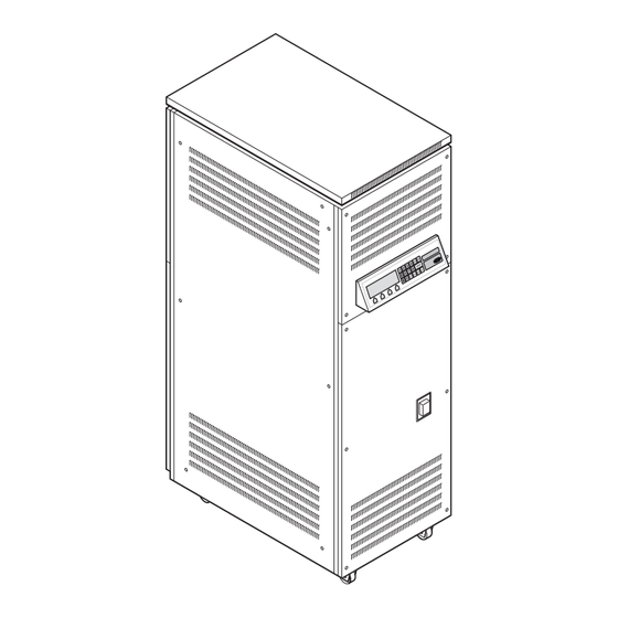
Description 3.4.7 Outside - big cabinet 20 to 30 kVA A Ventilation grids B HMI C Serial communication port D Manual switch E Remote control connector F Series output connection. The illustration shows the SCO. G Output to Series Circuit H Ethernet connector Power supply cable entry A.07.370e - Edition 2.0... -
Page 24: Inside - Big Cabinet 20 To 30 Kva
Description 3.4.8 Inside - big cabinet 20 to 30 kVa A Line filter B Input filter C Power supply PCB (EPS480) D Power supply transformer E CPU PCB (EPS479) F Sensing PCB (EPS476) G Diode Bridge H Main fuses Main contactor J IGBT-PCBs (EPS496) K IGBTs L Sensing transformer... -
Page 25: Outside - Big Cabinet: 20 To 30 Kva With Cs (Option Cs)
Description 3.4.9 Outside - big cabinet: 20 to 30 kVA with CS (option CS) A Ventilation grids B HMI C Serial communication port D Manual switch A.07.370e - Edition 2.0... -
Page 26: 10Inside - Big Cabinet: 20 To 30 Kva With Cs (Option Cs)
Description 3.4.10 Inside - big cabinet: 20 to 30 kVA with CS (option CS) Note The illustration shows only the items of the CS. For all other items, see § 3.4.4. A Interface PCB (PCB1702) B Power supply convertors for multiwire remote control C Input terminals D Lightning arrestors E CS PCB (PCB1619) -
Page 27: Components
Description 3.5 Components For the exact location and connectors see § 3.4 and the electrical scheme. You can find the electrical scheme attached on the outside of the equipment. 3.5.1 Line input Input terminal, all cabinets The input terminal connects the power input cables to the equipment. - Page 28 Description Main fuses, all cabinets The main fuses disconnect the equipment from the mains power supply if the input current is above a given value. Main contactor, stackable cabinet and small cabinet The main contactor allows the power supply PCB to automatically interrupt the power.
-
Page 29: Input Filter
Description Sensing transformer, all cabinets The sensing transformer measures the input voltage level of the line input. Power supply transformer, all cabinets The power supply transformer: Supplies the zero crossing signal determined from the input voltage. Provides the correct current and voltage to power all the electronic components such as PCBs and to power the fans (for 15 to 30kVA equipment). -
Page 30: Igbt Power Bridge
Description Input filter, 15 kVA small cabinet and big cabinet The input filter is a 12.5 kHz filter that blocks the noise the equipment produces from the line input at a different frequency than the line filter. 3.5.3 IGBT power bridge The IGBT power bridge has the components that follow: Diode bridge + sensing PCB IGBT PCB... - Page 31 Description Sensing PCB (EPS476), big cabinet The sensing PCB measures the AC input line and controls the diode bridge. Note In the big cabinet, the sensing PCB and the diode bridge are separate parts. IGBT, all cabinets An IGBT controls a high power via a low power electronic signal. The IGBT can switch at high frequency.
-
Page 32: Hall Sensor, Big Cabinet
Description 3.5.4 Hall sensor, big cabinet The Hall sensor measures the current between the IGBT and the output filter. 3.5.5 Output filter Output filter, stackable cabinets and small cabinet (except 15 kVA) The output filter is a Pulse Width Modulation (PWM) filter that builds the pure sine wave signal that comes from the H-bridge. -
Page 33: Main Transformer, All Cabinets
Description 3.5.6 Main transformer, all cabinets The main transformer converts the pure sine wave to the correct output voltage and current. 3.5.7 Output measure PCB (EPS422), all cabinets The output measure PCB measures the output voltage and current and sends these measurements to the CPU PCB. The EFD (See §... -
Page 34: Cpu Pcb (Eps479), All Cabinets
Description Connection to the series circuit There are mutual exclusive options possible. See §3.6. 3.5.9 CPU PCB (EPS479), all cabinets The CPU PCB Receives the measurement data of the output current and voltage from the output measure PCB via an optical fibre and compares these values with the required values. -
Page 35: 12Lamp Fault Detection (Lfd)
Description 3.5.12Lamp Fault Detection (LFD) The equipment analyses the output current and the voltage pattern to calculate, on a linear load, the number of open circuited lamps, in compliance with IEC 61822. The accuracy is ± 1 lamp with a range from 1 to 15 broken lamps. The HMI shows the actual LFD value. -
Page 36: Circuit Selector (Cs)
Description 3.6.3 Circuit selector (CS) With a CS you can connect several (up to eight) series circuits to a single equipment. The CS has two modes: Simultaneous: the equipment can connect to a number of the available circuits at the same time; Alternate: the equipment can connect to only one circuit at a time. -
Page 37: Hmi Sin Pcb (Pcb1703) (Option Cs)
Description 3.6.7 HMI SIN PCB (PCB1703) (option CS) Note This item is installed on the CS when the CS option is chosen. The HMI SIN BCB provides the indication of the state of the different series circuits (selected or not selected). 3.6.8 Remote control SIN PCB (PCB1694) (option CS) Note... -
Page 38: 10Current Sensor (Option Cs)
Description 3.6.10 Current sensor (option CS) Note This item is installed on the CS when the CS option is chosen. The current sensors sense if there runs current through the series circuits. 3.6.11 Series Connector Box (SCB), all cabinets The SCB connects the equipment to the series circuit with two medium voltage cables of the primary circuit. -
Page 39: 13Rolling Castors
Description 3.6.13 Rolling castors The equipment can be supplied with two fixed and two pivoting rolling castors to facilitate the movement of the equipment. The option is not available for stackable equipments or for an equipment with a CS. 3.7 HMI You can operate the equipment with the HMI. -
Page 40: Nameplate
Description 3.9 Nameplate Each equipment has a standard nameplate: SAFEGATE Constant Current Regulator DESCRIPTION: INPUT: OUTPUT: Remote CTRL: STEPS: OPTIONS: SERIAL NO: www.adbsafegate.com A.07.370e - Edition 2.0... -
Page 41: Inspection And Transport
Inspection and transport Inspection and transport 4.1 Inspect equipment on delivery Each equipment comes in a crate. 1. Check if the crate is not damaged. 2. If the crate is damaged, tell the carrier immediately. 3. Unpack the crates. See § 4.3. 4. -
Page 42: Transport The Unpacked Equipment
Use a rotation eye bolt to cover all applications with the same eye bolt type. Note Contact ADB Safegate for the correct eye bolt type. Prepare 1. Remove the bolts (A). 2. Install the lifting lugs (B). -
Page 43: Transport - Small And Big Cabinet With Wheels
Inspection and transport 4.4.2 Transport - small and big cabinet with wheels 1. Push the equipment to the applicable location. WARNING Make sure that the ground surface is flat and horizontal. A.07.370e - Edition 2.0... - Page 44 Inspection and transport A.07.370e - Edition 2.0...
-
Page 45: Pre-Installation
Pre-installation Pre-installation 5.1 How to pre-install - general procedure 1. Prepare the substation for the equipments. See § 5.2. 2. Prepare the lightning protection. See § 5.3. 3. Plan a power supply for each equipment. See § 5.4. 4. Plan the cables and the lay-out of the cables. See § 5.5. 5.2 Prepare substation 5.2.1 Procedure WARNING... -
Page 46: Substation Specifications
Pre-installation 5.2.2 Substation specifications For details on the substation specifications below, see ICAO Aerodome Design Manual, Part 5 Electrical Systems, DOC 9157-AN/901. Table: 5.1 Substation specifications Item Description Vault lighting Well illuminated for used day and night. Obey the local regulations. Shelter Clean and dry;... -
Page 47: Provide Heat Dissipation
Pre-installation 5.2.3 Provide heat dissipation Table: 5.2 Indicative values for heat dissipation Equipment [kVA] Heat dissipation [W] 1200 1400 1750 1800 1. Make sure that the heat dissipation efficiency is better than 90% for an equipment less than 30kVA and at least 92% for a 30kVA equipment. -
Page 48: Disconnection Devices
IEC: IEC 61822. 5.3 Prepare lightning protection 1. Examine the need for additional lightning protection. 2. If you need additional lightning protection, contact ADB Safegate to supply lightning diverters in accordance with IEC 61822. 5.4 Install power supply 1. Install a power supply for each equipment. -
Page 49: Plan The Cable Slack, Big And Small Cabinet (Option Cs)
Pre-installation 5.5.4 Plan the cable slack, big and small cabinet (option CS) 1. Plan the cable slack: Required cable slack from the bottom to the connection location: maximum 500 mm for the input power supply. maximum 400 mm for the output power supply. maximum 500 mm for the remote control cables. -
Page 50: Cables For Series Circuit
Pre-installation Table: 5.4 Wire sections and cable lengths for multiwire cables Diameter [mm] Typical Power supply Maximum cable Maximum cable length resistance at tolerance [%] length 48 V DC 24 V DC [km] 55 °C [Ohm/m] [km] 0.65 0.04 J-Bus cables (option) 1. -
Page 51: Installation
Installation Installation WARNING Always wear protective gloves and shoes when you do work on the equipment or the series circuit. WARNING Make sure that the power is OFF when you install the equipment. 6.1 Main installation procedure 1. Examine the pre-installation. See § 6.2. 2. -
Page 52: Required Meters
Installation 6.3.2 Required meters True RMS Multimeter; Isolating measurement transformer; CAUTION The output voltage of the 30 kVA / 6.6 A equipment can reach approximately 4600 V at full load. Insulation tester "Megger" 5000 V and 10000 V; AC True RMS measurement device (obey ICAO part 5 § 3.9.4.7). CAUTION The current regulation is +/- 1%. -
Page 53: Remove Lower Rear Panel, Big And Small Cabinet
Installation 6.6 Remove lower rear panel, big and small cabinet The panels of the equipment can be removed for installation or maintenance procedures. WARNING Do not operate the equipment with any of the panels removed. Do not mix panels from different equipments. Always connect the earthing wire before you install the panels. -
Page 54: Install Additional Earthing, Stackable Cabinet
Installation 6.7 Install additional earthing, stackable cabinet 1. Connect an earthing wire to the M8 earthing screw (A) at the rear of the cabinet. Use an earthing wire with a cross-section of at least 10 mm². The wire must be as short as possible. WARNING Earth the cabinet correctly. -
Page 55: Connect Power Input Supply, Stackable Cabinet
Installation 6.9 Connect power input supply, stackable cabinet Disassemble the connector 1. Remove the screws (A). 2. Remove the terminal block (B). Connect - 1 1. Put the cable gland over the input cable (A). 2. Put the input cable through the connector (B). 3. -
Page 56: Connect Power Input Supply, Big And Small Cabinet
Installation 6.10 Connect power input supply, big and small cabinet The connection is based on screw terminals. 1. Strip the input power supply cables. 208-230V input up to 10 kVA: 16 mm from 10 to 30 kVA: 18 mm 380-400V input up to 15 kVA: 16 mm from 15 to 30 kVA: 18 mm Connect - 1... -
Page 57: Connect Power Input Supply, Big And Small Cabinet With Cs (Option)
Installation 6.11 Connect power input supply, big and small cabinet with CS (option) The connection is based on screw terminals. 1. Strip the input power supply cables. 208-230V input up to 10 kVA: 16 mm from 10 to 30 kVA: 18 mm 380-400V input up to 15 kVA: 16 mm from 15 to 30 kVA: 18 mm... -
Page 58: Connect Output To Series Circuit
Installation 6.12 Connect output to series circuit CAUTION If the series circuit cable is screened, connect the screen to an earthing network either inside or outside the equipment. The procedures show how to connect the integrated output connections: With SCB (option). See § 6.12.1. With SCO (option). -
Page 59: 2Connect Output To Series Circuit With Sco
Installation Connect 1. Loosen the screws (B) of the cable guide (A). 2. Loosen the screws (D) of the stress-relief clamps (C) 3. Lead the series circuit cables (E) through the cable guide and through the stress-relief clamps. 4. Loosen the screws (F). 5. - Page 60 Installation Connect 1. Loosen the screws (A) of the cable guide (B). 2. Loosen the screws (C) of the stress-relief clamps (D) 3. Lead the series circuit cables (E) through the cable guide and through the stress-relief clamps. 4. Loosen the screws (F). 5.
-
Page 61: 3Connect Output To Series Circuit (Option Cs)
Installation 6.12.3 Connect output to series circuit (option CS) The number of terminals available for series circuit connections depends on your order. CAUTION Make sure you connect all terminals. If you do not want to use all terminals, put the free terminals into short-circuit. -
Page 62: Connect Remote Control Cables
Installation 1. Remove the screws (A). 2. Remove the protection plate (B). 3. Strip the cables at the end. In the case of a screened cable, remove the outer sheet of the cable between the terminals and the earthing bar. 4. -
Page 63: 2Connect Ethernet Cable(S) (Option)
Installation Connect - 1 1. Put the remote control wire (A) through the connector (B). 2. Strip the signal wires (C) approximately 100 mm. 3. Connect the signal wires to the terminal blocks. For the connection scheme, see § 7.8.3. 4. - Page 64 Installation A.07.370e - Edition 2.0...
-
Page 65: Technical Data
RMS output voltage Insulated test on Output overvoltage power [kW] at 6.6 A RMS output output [kV] protection 25kApk current [kV] CRE 2.5 2.5 0.38 0.75 kV , 1.4 kJ CRE 4.0 4.0 0.60 1.5 kV , 2.8 kJ CRE 5.0 5.0 0.75... -
Page 66: Applicable Standards
Technical data Type Rated output RMS output voltage Insulated test on Output overvoltage power [kW] at 6.6 A RMS output output [kV] protection 25kApk current [kV] CRE 10 10.0 1.50 2.2 kV , 4.2 kJ CRE 15 15 2.30 3.0 kV , 5.6 kJ CRE 20 20 3.03... -
Page 67: Ambient Conditions
Technical data 7.4 Ambient conditions The equipment is air-cooled with fans. Thus, the equipment must have a good airflow, especially if they operate near the maximum temperature. Table: 7.4 Ambient conditions Item Description Temperature From -20 up to +55 °C Altitude From 0 (sea level) up to 1000 meter Relative humidity... -
Page 68: Dimensions And Mass
Technical data 7.5 Dimensions and mass The stackable cabinet (A), the small cabinet (B) and the big cabinet (C): Table: 7.5 Dimensions Item A - 2.5 kVA B - 2.5 kVA B - 4 to 15 kVA C - 20 to 30 kVA (stackable) X [mm] Y [mm]... - Page 69 Technical data Table: 7.6 Mass Type Net mass Crate mass Crate dimensions width x depth x height [mm] 2.5 (rack) 600 x 1000 x 650 1200 x 800 x 1500 1200 x 800 x 1500 1200 x 800 x 1500 1200 x 800 x 1500 1200 x 800 x 1500 1200 x 800 x 1500...
-
Page 70: Substation Layout
Technical data 7.6 Substation layout 7.6.1 Substation layout, stackable cabinet Table: 7.7 Clearance specifications Clearance specification Distance [mm] Front clearance Approximately 500 Between the rear of the machine and the wall, X Approximately 500 Between two machines (side by side), or between Minimum 150 another machine, Y If necessary, the distances can be increased for maintenance purposes. -
Page 71: Substation Layout, Big And Small Cabinets
Technical data 7.6.2 Substation layout, big and small cabinets Table: 7.8 Clearance specifications Clearance specification Distance [mm] Front clearance Approximately 500 Between the rear of the machine and the wall, X Approximately 500 Between two machines (side by side) or between Minimum 150 another machine, Y If necessary, the distances can be increased for maintenance purposes. - Page 72 Technical data Equipment Equipment voltage Main fuse rating [A] Manual switch type Maximum line input type [kVA] C rating [A] current [A] 380 to 400 32.1 380 to 400 48.1 380 to 400 64.2 380 to 400 80.2 380 to 400 96.2 A.07.370e - Edition 2.0...
-
Page 73: Remote Control Pcb (Eps495)
Technical data 7.8 Remote control PCB (EPS495) 7.8.1 Printed Circuit Board (PCB) 7.8.2 Jumper settings Table: 7.10 Remote control PCB jumper settings Jumper Position Function insert enable TX serial channel 1 termination resistance insert enable RX serial channel 1 termination resistance insert enable TX serial channel 2 termination resistance insert... - Page 74 Technical data Jumper Position Function position 1-3 and position 2-4 ethernet channel 2: enable position 3-5 and position 4-6 serial channel 2: enable position 2-3 serial channel 1: RS485 configuration position 1-2 serial channel 1: RS422 configuration (not used) position 2-3 serial channel 1: RS485 configuration position 1-2 serial channel 1: RS422 configuration (not used)
-
Page 75: Multiwire / J-Bus Connection Scheme
Technical data 7.8.3 Multiwire / J-Bus connection scheme 25 17 Note The table below shows the standard remote control configuration for the signals. If you want another configuration, contact ADB Safegate. 32 24 16 8 A.07.370e - Edition 2.0... - Page 76 Technical data Table: 7.11 Factory set terminal assignments for remote control connections with multiwire and single J-Bus Function Terminal number on 32-pole Relay number on Remote Control connector PCB (unless indicated otherwise) Control signals (fixed) Step 1 J1.1 Step 2 J1.2 Step 3 J1.3...
- Page 77 Technical data Function Terminal number on 32-pole Relay number on Remote Control connector PCB (unless indicated otherwise) J-Bus interface (fixed) RS485 BusA GND DB9.3 RS485 Data - DB9.2 RS485 Data + DB9.1 Configurable with HMI Table: 7.12 Factory set terminal assignments for remote control connections with multiwire dual J- Function Terminal number on 32-pole Relay number on Remote Control...
- Page 78 Technical data Function Terminal number on 32-pole Relay number on Remote Control connector PCB (unless indicated otherwise External signals (fixed) J-Bus interface (fixed) RS485 BusA GND DB9.3 RS485 Data - DB9.2 RS485 Data + DB9.1 RS485 BusB GND DB92.3 RS485 Data + DB92.1 RS485 Data - DB92.2...
- Page 79 Technical data Multiwire and J-Bus connection A Equipment B Remote control equipment C Remote control PCB - input signals D Remote control connector on the equipment E Opto coupler F 48 V DC power supply G Isoground H +48 V DC Rel com J Remote control PCB - feedback signals K Relais...
-
Page 80: Interface Pcb (Pcb1702) (Option Cs)
Technical data 7.9 Interface PCB (PCB1702) (option CS) 7.9.1 Printed Circuit Board (PCB) RJ45 7.9.2 Jumper J2 Installed: more than one series circuit Not installed: only one series circuit 7.9.3 Connectors Table: 7.13 CS connectors Connector Connection to Connection Description point Flat cable connection to EPS495 (remote control PCB) Connection to CS PCB... - Page 81 Technical data Connector Connection to Connection Description point Remote control multiwire CS1RC Remote control input circuit 1 connection CS2RC Remote control input circuit 2 CS3RC Remote control input circuit 3 CS5RC Remote control input circuit 4 CS5RC Remote control input circuit 5 CS6RC Remote control input circuit 6 CS7RC...
- Page 82 Technical data Connector Connection to Connection Description point Remote control multiwire CS1FB Feedback circuit 1 connection CS2FB Feedback circuit 2 CS3FB Feedback circuit 3 CS4FB Feedback circuit 4 CS5FB Feedback circuit 5 CS6FB Feedback circuit 6 CS7FB Feedback circuit 7 CS8FB Feedback circuit 8 CSE-FLT...
- Page 83 Technical data Connector Connection to Connection Description point Remote control multiwire B1FB Feedback equipment, configurable spare connection J5.1 B2FB Feedback equipment, configurable spare J5.2 B3FB Feedback equipment, configurable spare J5.3 B4FB Feedback equipment, configurable spare J5.4 B5FB Feedback equipment, configurable spare J5.5 ON_FB Feedback equipment ON...
- Page 84 Technical data Table: 7.15 LEDs that indicate the interface functionality Function LED ‘CRE_ON_IN’.The LED is ON if the equipment is operational and supplies power to the output circuit. LED J5.7 IN. The LED is ON if the equipment is in remote mode. LED J7.1 IN.
- Page 85 Technical data A.07.370e - Edition 2.0...
- Page 86 adbsafegate.com...
Need help?
Do you have a question about the CRE 2.5 and is the answer not in the manual?
Questions and answers