Sign In
Upload
Manuals
Brands
ADB Safegate Manuals
Controller
CRE 2.5
ADB Safegate CRE 2.5 Manuals
Manuals and User Guides for ADB Safegate CRE 2.5. We have
1
ADB Safegate CRE 2.5 manual available for free PDF download: Installation Manual
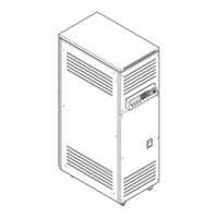
ADB Safegate CRE 2.5 Installation Manual (86 pages)
Constant Current Regulator
Brand:
ADB Safegate
| Category:
Controller
| Size: 14 MB
Table of Contents
Table of Contents
3
About this Manual
7
How to Work with the Manual
7
Record of Changes
7
Icons Used in the Manual
7
Abbreviations and Terms
8
Safety
9
Use
9
Safety Symbols
9
Signs on the Equipment
10
Skilled Personnel
10
Liability
11
Installation
11
Operation
12
Use of the Optional Circuit Selector Cabinet
12
Action in the Event of an Equipment Malfunction
12
Maintenance and Repair
12
CE Certification
13
Guarantee
13
Description
15
Series Circuit System Overview
15
Intended Use
15
Working Principle
16
Lay-Out of the Equipment Cabinet
17
Outside - Stackable Cabinet 2.5 Kva
17
Inside - Stackable Cabinet 2.5 Kva
18
Outside - Small Cabinet: 2.5 to 15 Kva
19
Inside - Small Cabinet: 2.5 to 15 Kva
20
Outside - Small Cabinet: 2.5 to 15 Kva with CS (Option CS)
21
Inside - Small Cabinet: 2.5 to 15 Kva with CS (Option CS)
22
Outside - Big Cabinet 20 to 30 Kva
23
Inside - Big Cabinet 20 to 30 Kva
24
Outside - Big Cabinet: 20 to 30 Kva with CS (Option CS)
25
10Inside - Big Cabinet: 20 to 30 Kva with CS (Option CS)
26
Components
27
Line Input
27
Input Filter
29
IGBT Power Bridge
30
Hall Sensor, Big Cabinet
32
Output Filter
32
Main Transformer, All Cabinets
33
Output Measure PCB (EPS422), All Cabinets
33
Power Output
33
CPU PCB (EPS479), All Cabinets
34
10Remote Control PCB (EPS495), All Cabinets
34
Power Supply PCB (EPS480), All Cabinets
34
12Lamp Fault Detection (LFD)
35
13Earth Fault Detection (EFD)
35
Options
35
Remote Control
35
Ethernet PCB (EPS542), All Cabinets
35
Circuit Selector (CS)
36
Lightning Arrestors (Option CS)
36
Interface PCB (PCB1702) (Option CS)
36
CS PCB (PCB1619) (Option CS)
36
HMI sin PCB (PCB1703) (Option CS)
37
Remote Control sin PCB (PCB1694) (Option CS)
37
CS Relay (Option CS)
37
10Current Sensor (Option CS)
38
Series Connector Box (SCB), All Cabinets
38
12Series Cutout (SCO), All Cabinets
38
13Rolling Castors
39
Hmi
39
HMI of an Equipment with CS (Option CS)
39
Nameplate
40
Inspection and Transport
41
Inspect Equipment on Delivery
41
How to Transport the Crate
41
Unpack at Installation Area
41
Transport the Unpacked Equipment
42
Transport the Equipment with Lifting Lugs
42
Transport - Small and Big Cabinet with Wheels
43
Pre-Installation
45
How to Pre-Install - General Procedure
45
Prepare Substation
45
Procedure
45
Substation Specifications
46
Provide Heat Dissipation
47
Ventilation
47
External Fuse
47
Circuit Breakers
47
Disconnection Devices
48
Prepare Lightning Protection
48
Install Power Supply
48
Plan Cables and Lay-Out of Cables
48
Procedure
48
Plan the Cable Slack, Stackable Cabinet
48
Plan the Cable Slack, Big and Small Cabinet
48
Plan the Cable Slack, Big and Small Cabinet (Option CS)
49
Power Supply Cables and Earthing Cables
49
Plan Cables to the Remote Control Interface
49
Cables for Series Circuit
50
Installation
51
Main Installation Procedure
51
Check Pre-Installation
51
Required Tools and Equipment
51
Required Safety Items
51
Required Meters
52
Required Tools
52
Required Cables
52
Inspection
52
Switch off the Power Supply
52
Remove Lower Rear Panel, Big and Small Cabinet
53
Install Additional Earthing, Stackable Cabinet
54
Install Additional Earthing, Big and Small Cabinet
54
Connect Power Input Supply, Stackable Cabinet
55
Connect Power Input Supply, Big and Small Cabinet
56
Connect Power Input Supply, Big and Small Cabinet with CS (Option)
57
Connect Output to Series Circuit
58
1Connect Output to Series Circuit with SCB
58
2Connect Output to Series Circuit with SCO
59
3Connect Output to Series Circuit (Option CS)
61
Connect Remote Control Cables
62
1Connect Multiwire or J-Bus (Option)
62
2Connect Ethernet Cable(S) (Option)
63
3Connect the Multiwire Cables to the Interface PCB (PCB1702) (Option CS)
63
Install Lower Rear Panel
63
Technical Data
65
Specifications
65
Applicable Standards
66
Electromagnetic Compatibility (EMC)
66
Ambient Conditions
67
Dimensions and Mass
68
Substation Layout
70
Substation Layout, Stackable Cabinet
70
Substation Layout, Big and Small Cabinets
71
Protection Devices
71
Remote Control PCB (EPS495)
73
Printed Circuit Board (PCB)
73
Jumper Settings
73
Multiwire / J-Bus Connection Scheme
75
Interface PCB (PCB1702) (Option CS)
80
Advertisement
Advertisement
Related Products
ADB Safegate CRE 4.0
ADB Safegate CRE 5.0
ADB Safegate CRE 7.5
ADB Safegate CRE 10
ADB Safegate CRE 15
ADB Safegate CRE 20
ADB Safegate CRE 30
ADB Safegate CRE Series
ADB Safegate CRE
ADB Safegate IDM 8000
ADB Safegate Categories
Lighting Equipment
Controller
GPS
Measuring Instruments
Control Systems
More ADB Safegate Manuals
Login
Sign In
OR
Sign in with Facebook
Sign in with Google
Upload manual
Upload from disk
Upload from URL