Table of Contents
Advertisement
Quick Links
www.teledyne-hi.com
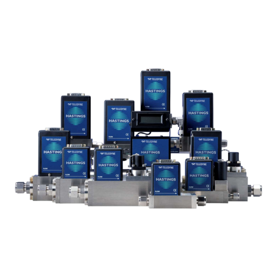
HFM-301/305/306 Flow Meters
HFC-303/307 Flow Controllers
INSTRUCTION MANUAL
I S O 9 0 0 1
C E R T I F I E D
Use and Disclosure of Data
Information contained herein is classified as EAR99 under the U.S. Export Administration Regulations.
Export, reexport or diversion contrary to U.S. law is prohibited.
Advertisement
Table of Contents

Related Manuals for Teledyne HFM-301


Summary of Contents for Teledyne HFM-301
- Page 1 HFM-301/305/306 Flow Meters HFC-303/307 Flow Controllers INSTRUCTION MANUAL I S O 9 0 0 1 C E R T I F I E D Use and Disclosure of Data Information contained herein is classified as EAR99 under the U.S. Export Administration Regulations.
- Page 2 Revision U (Document Number 152-042017) ............................April 2017 Revision U (Document Number 152-042017) ..........................August 2022 Visit www.teledyne-hi.com for WEEE disposal guidance. Description of Symbols and Messages used in this manual WARNING: indicates a hazardous situation, which, if not avoided, could result in death or serious injury.
-
Page 3: Table Of Contents
301/303/305/306/307 Flowmeters and Controllers Instruction Manual Table of Contents GENERAL INFORMATION ....................5 ......................6 EATURES ......................7 PECIFICATIONS 4-20 .................. 9 PTIONAL URRENT UTPUT ......................10 CCESSORIES 1.4.1. Power Supplies....................10 1.4.2. Cables ......................10 INSTALLATION AND SETUP .................... 11 .................... - Page 4 .................... 27 ARRANTY EPAIR OLICY ...................... 27 ETURN OLICY DRAWINGS ........................ 28 HFM-301 ......................28 HFC-303 ......................29 HFM-305 ......................30 HFM-306 ......................31 HFC-307 ......................32 EAR99 Technology Subject to Restrictions Contained on the Cover Page Page 4 of 32...
-
Page 5: General Information
301/303/305/306/307 Flowmeters and Controllers Instruction Manual 1. General Information The Hastings 300 series high range mass flow meters and controllers are designed to accurately measure and control mass flow at ranges between 25 slm and 10,000 slm with an accuracy of better than ±1% Full Scale (HFM-306 is 2% FS). -
Page 6: Features
301/303/305/306/307 Flowmeters and Controllers Instruction Manual Features LINEAR BY DESIGN. The HFM-301/305/306 and HFC-303/307 series are intrinsically linear (no linearization circuitry is employed). Should field recalibration (a calibration standard is required) be desired, the customer needs to simply set the zero and span points. There will be no appreciable linearity change of the instrument when the flowing gas is changed. -
Page 7: Specifications
WARNING: Do not operate instruments exceeding the specifications listed below. Failure to heed this warning could result in serious personal injury and/or damage to the equipment. Accuracy: HFM-301/305 & HFC-303/307: ±1% FS (±2% FS for HFM-306) Repeatability: ±0.2% FS Standard Pressure Rating: HFM-301, HFC-303: 500 psig [3.45 MPa]... - Page 8 HFM-306 = 28.8 lbs. [13.1 kg] HFC-301 = 15.2 lbs. [6.9 kg] Electrical Connector: 15 pin subminiature “D” Fitting Options: HFM-301/HFC-303: ½”, ¾” tube, 10, 12, 20 mm tube, 3/8”, ½” Male ® ® NPT, ½” and ¾” VCR and VCO , ¾-16 and 1-1/16 MS straight female,...
-
Page 9: Optional 4-20 Ma Current Output
301/303/305/306/307 Flowmeters and Controllers Instruction Manual Optional 4-20 mA Current Output An option to the standard 0-5 VDC output is the 4-20 mA current output that is proportional to flow. The 4-20 mA signal is produced from the 0-5 VDC output of the flow meter. The current loop output is useful for remote applications where pickup noise could substantially affect the stability of the voltage output or long cable runs where cable resistance would cause a voltage signal to decay. -
Page 10: Accessories
For knowledge of the most up-to-date Hastings power supplies, please consult either Hastings sales staff or our website at http://www.teledyne-hi.com WARNING: To prevent the spread of fires in the event of a fault, only use power supplies power limited to no more than 150 VA. -
Page 11: Installation And Setup
7. Instrument is ready for operation Power Requirements At their maximum power draws, the HFM-301/305/306/307 meters require ±15 VDC @ 70 mA, and the HFC- 303/307 controllers require ±15 VDC @ 185 mA (See specifications in sections 1.2). The HFM-300/HFC-302 Series supply voltages should be reasonably regulated as power supply ripple may propagate to the output (less than 50 mV ripple is preferred). -
Page 12: Mechanical Connections
301/303/305/306/307 Flowmeters and Controllers Instruction Manual Mechanical Connections 2.4.1. Gas Quality (Filtering) Impurities or foreign debris in the gas lines can have negative effects on device performance. The smallest of the internal passageways in the HFM-300/HFC-302 Series is the diameter of the sensor tube, which can be 0.026”... -
Page 13: Electrical Connections
301/303/305/306/307 Flowmeters and Controllers Instruction Manual Electrical Connections If a power supply from Hastings Instruments is used, installation consists of connecting the 300 series cable from the “D” connector on the rear of the power supply to the “D” connector on the top of the flow meter/controller. - Page 14 301/303/305/306/307 Flowmeters and Controllers Instruction Manual Figures 2.1/2.2, and Tables 2.1/2.2, show the 300/302 pin out. Ta ble 2.1 Ta ble 2.2 "U" Pin-Out "H" Pin-Out Pin # Pin # Signal Common Do not use Do not use Do not use Do not use Do not use +15 VDC...
-
Page 15: Operation
301/303/305/306/307 Flowmeters and Controllers Instruction Manual Operation The standard instrument output signal is 0 - 5 VDC and is proportional to the flow (0 volts = zero flow, 5 Volts = 100% flow). The 4 - 20 mA option is also proportional to flow (4 mA = zero flow and 20 mA = 100% flow). 2.6.1. - Page 16 301/303/305/306/307 Flowmeters and Controllers Instruction Manual EAR99 Technology Subject to Restrictions Contained on the Cover Page Page 16 of 32...
- Page 17 301/303/305/306/307 Flowmeters and Controllers Instruction Manual If the system pressure is higher than 250 psig (1.7 MPa) the pressure induced error in the span reading becomes significant. This error will approach 16% for nitrogen at 1000 psig. For accurate high-pressure measurements this error must be corrected.
-
Page 18: Vertical Mounting
301/303/305/306/307 Flowmeters and Controllers Instruction Manual 2.6.4. Vertical Mounting It is not recommended to mount the instrument vertically if high pressure or high density gas is being measured. If the instrument is not mounted in a level position and is operating at high pressure or with high density gases, the increased gas density will cause convection to flow through the sensor tube. -
Page 19: Output Filter
301/303/305/306/307 Flowmeters and Controllers Instruction Manual SOLUTION: Use the formulas above: ( 0.05 )( 100 )( 5 ) �������� ���������� = 5% = 0.05, ���������� ������������ = = 0.5 ( 10 )( 5 ) Scale the output of controller A by 0.5 (half) and route the signal to the setpoint of controller B to flow 5% of controller A. -
Page 20: Controlling Other Process Variables (External Input)
301/303/305/306/307 Flowmeters and Controllers Instruction Manual Controlling Other Process Variables (External Input) Flow controllers usually control mass flow. The control loop opens and closes the valve to make the output flow signal match the command signal. Occasionally, gas is added or removed from a system to control some other process variable. -
Page 21: Gain Potentiometer
301/303/305/306/307 Flowmeters and Controllers Instruction Manual Gain Potentiometer On the top left of inlet side of the flow controller there is a hole through which the gain potentiometer is accessible (See right). This gain potentiometer affects the gain of the closed loop controller. Normally this potentiometer will be set at the factory for good stable control. -
Page 22: Maintenance
301/303/305/306/307 Flowmeters and Controllers Instruction Manual 3. Maintenance This section contains service and calibration information. Some portions of the instrument are delicate, so please use extreme care when servicing the flow controller. NOTICE: It may prove more prudent in the long run to delegate the maintenance of Hastings flow instruments to Hastings personnel who have the appropriate equipment and training. - Page 23 301/303/305/306/307 Flowmeters and Controllers Instruction Manual Symptom: Output of flow meter is proportional to flow, but extremely small and not correctable by span pot. Cause: Sensor is not being heated. Action: Shut off gas supply and disconnect the power to the flow meter.
-
Page 24: Adjustments (Calibration Procedure)
Disconnect the fittings on the inlet and outlet sides of the transducer and remove it from the system plumbing. On the HFM-301/305 and HFC-303/307, Remove the four screws holding the end cap to the instrument. Carefully remove the end cap, spring, and shunt, noting their order and proper orientation. -
Page 25: Printed Circuit Board Replacement
Remove the fasteners and steel can. The 4-20 mA board is the PC board marked PC854 in the lower left-hand corner just above the Teledyne logo. Remove the screws and lift off the 4-20 mA board. Be careful not to damage the main board and 4-20 mA board connectors. -
Page 26: Gas Conversion Factors
* (1.0015/0.3499) = 57.2449 slm Air Gas conversion factors can be found at the Hastings Instruments web site. http://www.teledyne-hi.com Follow the link to Mass Flow Products and then to Gas Conversion Factors. EAR99 Technology Subject to Restrictions Contained on the Cover Page... -
Page 27: Warranty And Repair
RMA Forms may be obtained from the Information section of the Hastings Instruments website: http://www.teledyne-hi.com/inforeq.htm WARNING: Contaminated parts can be detrimental to health and environment. Ensure instruments are free of hazardous contamination prior to shipment. Company contact information TELEDYNE HASTINGS INSTRUMENTS 804 NEWCOMBE AVENUE HAMPTON, VIRGINIA 23669 U.S.A. ATTENTION: REPAIR DEPARTMENT TELEPHONE... - Page 28 301/303/305/306/307 Flowmeters and Controllers Instruction Manual 6. Drawings The following pages display the top level drawing dimensions for the HFM-301, 305, 306, and the HFC-303, 307. HFM-301 EAR99 Technology Subject to Restrictions Contained on the Cover Page Page 28 of 32...
- Page 29 301/303/305/306/307 Flowmeters and Controllers Instruction Manual HFC-303 EAR99 Technology Subject to Restrictions Contained on the Cover Page Page 29 of 32...
- Page 30 301/303/305/306/307 Flowmeters and Controllers Instruction Manual HFM-305 EAR99 Technology Subject to Restrictions Contained on the Cover Page Page 30 of 32...
- Page 31 301/303/305/306/307 Flowmeters and Controllers Instruction Manual HFM-306 EAR99 Technology Subject to Restrictions Contained on the Cover Page Page 31 of 32...
- Page 32 301/303/305/306/307 Flowmeters and Controllers Instruction Manual HFC-307 EAR99 Technology Subject to Restrictions Contained on the Cover Page Page 32 of 32...
Need help?
Do you have a question about the HFM-301 and is the answer not in the manual?
Questions and answers