
Related Manuals for Teledyne HASTINGS HFM-300


Summary of Contents for Teledyne HASTINGS HFM-300
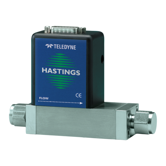
- Page 1 TELEDYNE HASTINGS INSTRUMENTS INSTRUCTION MANUAL HFM-300 FLOW METER, HFC-302 FLOW CONTROLLER I S O 9 0 0 1 C E R T I F I E D...
- Page 2 Revision M (Document Number 151-082010) ..............August 2010 Revision P (Document Number 151-062012) ..............June 2012 Revision Q (Document Number 151-032015)…………………………………………………March 2015 Visit www.teledyne-hi.com for WEEE disposal guidance. The instruments described in this manual are available with multiple pin-outs. CAUTION: Ensure that all electrical connections are correct.
-
Page 3: Table Of Contents
Table of Contents GENERAL INFORMATION ............................4 1.1..................................4 EATURES 1.2................................5 PECIFICATIONS 4-20 PTIONAL URRENT UTPUT 1.3..........................5 THER CCESSORIES 1.4............................... 6 1.4.1. Hastings Power supplies ............................ -
Page 4: General Information
1. General Information The Teledyne Hastings HFM-300 is used to measure mass flow rates in gases. In addition to flow rate measurement, the HFC-302 includes a proportional valve to accurately control gas flow. The Hastings mass flow meter (HFM-300) and controller (HFC-302), hereafter referred to as the Hastings 300 series, are intrinsically linear and are designed to accurately measure and control mass flow over the range of 0-5 sccm to 0-10 slm with an accuracy of better than ±0.75% F.S. -
Page 5: Specifications
1.2. Specifications Accuracy..................< ±0.75% full scale (F.S.) at 3 (±1.0% F.S. for >10 slm versions) Repeatability (includes noise) ................±0.2% F.S. Maximum Pressure ..................500 psi [3.45 MPa] (With high pressure option) 1000 psi [6.9 MPa] Pressure Coefficient ..........<0.016% of reading/psi [0.0015%/kPa] (N2) See pressure section for higher pressure errors Operating Temperature .......... -
Page 6: Other Accessories
With the PowerPod 400, individual channels’ input signals, as well as their commands, become 4–20 mA compatible when selected. The PowerPod-400 also sports a Totalizer feature. More information about the Power Pods can be found on the Hastings web site. http://www.teledyne- hi.com/products/powerpod-series.htm 1.4.2. -
Page 7: Installation And Operation
2. Installation and Operation This section contains the steps necessary to assist in getting a new flow meter/controller into operation as quickly and easily as possible. Please read the following thoroughly before attempting to install the instrument. 2.1. Receiving Inspection Carefully unpack the Hastings unit and any accessories that have also been ordered. -
Page 8: Mechanical Connections
2.4. Mechanical Connections 2.4.1. Filtering The smallest of the internal passageways in the Hastings 300 is the diameter of the sensor tube, which is 0.026”(0.66 mm), and the annular clearance for the 500 sccm shunt which is 0.006"(0.15 mm) (all other flow ranges have larger passages), so the instrument requires adequate filtering of the gas supply to prevent blockage or clogging of the tube. -
Page 9: Operation
Fig. 2.1 Fig. 2.2 Figures 2.1/2.2, and Tables 2.1/2.2, show the 300/302 pin out. Table 2.1 Table 2.2 "U" Pin-Out "H" Pin-Out Pin # Pin # Signal Common Do not use Do not use Do not use Do not use Do not use +15 VDC Do not use... -
Page 10: Zero Check
2.6.2. Zero Check Turn the power supply on if not already energized. Allow for a 1 hour warm-up. Stop all flow through the instrument and wait 2 minutes. Caution: Do not assume that all metering valves completely shut off the flow. Even a slight leakage will cause an indication on the meter and an apparent zero shift. - Page 11 Page 11 of 22 Manual: 151-032015 300-302 Series...
-
Page 12: Vertical Mounting
If the system pressure is higher than 250 psig (1.7 MPa) the pressure induced error in the span reading becomes significant. This error will approach 16% for nitrogen at 1000 psig. For accurate high pressure measurements this error must be corrected. The formula for predicting the nitrogen mean error expressed as a fraction of the reading are: ... -
Page 13: Output Filter
EXAMPLE: Flow controller A has 0-100 slpm range with a 5.00 volt output at full scale. Flow controller B has 0-10 slpm range with a 5.00 volt output at full scale. If flow controller A is set at 80 slpm, its output voltage would be 4.00 volts (80 slpm/100 slpm x 5.00 volts = 4.00 volts). If the output signal from flow controller A is connected to the command Set Point of flow controller B, then flow controller B becomes a slave to the flow signal of controller A. -
Page 14: Command Input
variable directly. This analog output signal could be 0-5 volts, 0-10 volts (or 4-20 ma for units with 4- 20 ma boards) or any value in between. On the controller card there is a jumper that sets whether the control loop controls mass flow or an external process variable. - Page 15 temperature, errors will be introduced into the output of the instrument. The Temperature Coefficient of Zero describes the change in the output that is seen at zero flow. This error is added to the overall output signal regardless of flow, but can be eliminated by adjusting the zero potentiometer of the flow meter/controller to read zero volts at zero flow conditions.
-
Page 16: Maintenance
3. Maintenance This section contains service and calibration information. Some portions of the instrument are delicate. Use extreme care when servicing the instrument. Authorized Maintenance With proper care in installation and use, the instrument will require little or no maintenance. If maintenance does become necessary, most of the instrument can be cleaned or repaired in the field. -
Page 17: Adjustments
Symptom: flow meter reads other than 0.00 VDC with no flow or there is a small flow when the flow meter reads 0.00 VDC. Cause: Zero pot is out of adjustment. Action: Shut off all flow. For the standard 0-5VDC output, adjust the zero potentiometer located on the upper right inlet side of the flow meter until the meter indicates zero. -
Page 18: Printed Circuit Board Replacement
Remove the fasteners and steel can. The 4-20 mA board is the PC board marked PC854 in the lower left-hand corner just above the Teledyne logo. Remove the screws and lift off the 4-20 mA board. Be careful not to damage the main board and 4-20 mA board connectors. -
Page 19: Gas Conversion Factors
4. Gas Conversion Factors Gas conversion factors (GCF’s) for gasses metered using Hastings Instruments products, can be found by visiting the Hastings Instruments web site. The web address can be found at the end of this document. The gas conversion factors (GCF's) provided by Hastings Instruments (HI) fall into five basic accuracy domains that, to a large extent, are dependent on the method by which they are found. - Page 20 20 * (1.0015/0.3499) = 57.2449 Gas conversion factors can be found at the Hastings Instruments web site. http://www.teledyne-hi.com Follow the link to Mass Flow Products and then to Gas Conversion Factors. Page 20 of 22...
-
Page 21: Volumetric Vs Mass Flow
5. Volumetric Vs Mass Flow Mass flow measures just what it says, the mass or number of molecules of the gas flowing through the instrument. Mass flow (or weight per unit time) units are given in pounds per hour (lb/hour), kilograms per sec (kg/sec) etc. -
Page 22: Warranty
If you then choose not to have the product repaired, a minimum will be charged to cover the processing and inspection. Please consult the factory for your RMA number before returning any product repair. TELEDYNE HASTINGS INSTRUMENTS 804 NEWCOMBE AVENUE HAMPTON, VIRGINIA 23669 U.S.A.
Need help?
Do you have a question about the HASTINGS HFM-300 and is the answer not in the manual?
Questions and answers