Table of Contents
Advertisement
Quick Links
Mounting and operating instructions
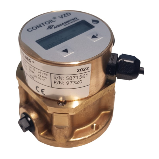
CONTOIL
VZD2 / VZDA2, DN 4 - 8
Table of Contents
1
Safety............................................................................................................................. 3
1.1
Intended Use ............................................................................................................................................................ 3
1.2
Notes on safety rules and symbols .................................................................................................................. 3
1.3
Safety rules and precautions .............................................................................................................................. 4
1.4
About the operating manual .............................................................................................................................. 4
2
Scope of delivery and accessories .............................................................................. 5
3
Product description ..................................................................................................... 5
3.1
Application ................................................................................................................................................................ 5
3.2
Device components ............................................................................................................................................... 5
3.3
Power supply ............................................................................................................................................................ 5
3.4
Interfaces .................................................................................................................................................................... 5
4
Mounting ...................................................................................................................... 6
5
Installation .................................................................................................................... 6
5.1
Mechanical Installation ......................................................................................................................................... 6
5.2
Electrical Installation ............................................................................................................................................ 10
6
Commissioning ........................................................................................................... 10
6.1
Display ....................................................................................................................................................................... 11
6.2
Operation of flow meter .................................................................................................................................... 12
6.3
General overview of Menu structure ............................................................................................................. 13
6.4
Counters and instant values ............................................................................................................................. 14
6.5
Information ,Operating hours and Billing .................................................................................................... 15
6.6
Loggers, unlock and Logbook ......................................................................................................................... 16
6.7
Output settings ...................................................................................................................................................... 17
6.8
Internal bus communication ............................................................................................................................. 18
6.9
Units ........................................................................................................................................................................... 19
6.10
Configuration and System settings ................................................................................................................ 20
6.11
System information .............................................................................................................................................. 21
7
Maintenance and Repair ........................................................................................... 22
7.1
Calibration ............................................................................................................................................................... 22
7.2
Service maintenance ............................................................................................................................................ 22
7.3
Spare parts .............................................................................................................................................................. 22
8
Troubleshooting and error messages ...................................................................... 23
8.1
Troubleshooting .................................................................................................................................................... 23
8.2
Alarm messages .................................................................................................................................................... 24
8.3
Error messages ....................................................................................................................................................... 24
9
Decommissioning, Dismantling and Disposal ........................................................ 25
9.1
Decommissioning ................................................................................................................................................. 25
9.2
Dismantling ............................................................................................................................................................. 25
9.3
Disposal .................................................................................................................................................................... 25
®
Advertisement
Table of Contents

Subscribe to Our Youtube Channel
Related Manuals for Aquametro Oil & Marine CONTOIL VZD2


Summary of Contents for Aquametro Oil & Marine CONTOIL VZD2
-
Page 1: Table Of Contents
Mounting and operating instructions CONTOIL ® VZD2 / VZDA2, DN 4 - 8 Table of Contents Safety..........................3 Intended Use ................................3 Notes on safety rules and symbols ........................3 Safety rules and precautions ..........................4 About the operating manual ..........................4 Scope of delivery and accessories ................ - Page 2 Technical Data ......................26 10.1 Model code ................................26 10.2 Hardware characteristics ............................ 27 10.3 Electronic characteristics ............................ 27 10.4 Communication types ............................28 Appendix ........................31 11.1 Dimensional drawings ............................31 11.2 Modbus addressing ............................. 32 11.3 M-Bus addressing ..............................33 11.4 Settings list ................................
-
Page 3: Safety
1 Safety 1.1 Intended Use The device CONTOIL ® VZD2 is designed and solely intended for the flow and consumption meas- urement of Diesel oil and Lubrication oil. Improper or non-intended use of the device may compromise operational reliability of the device. The manufacturer accepts no liability for any resulting personal injury or material damage. -
Page 4: Safety Rules And Precautions
1.3 Safety rules and precautions The manufacturer accepts no responsibility if the following safety rules and precautions are disregarded: Any modifications of the device implemented without the prior written consent of the manufacturer will result in the immediate termination of product liability and warranty. Installation, operation, maintenance and decommissioning of this device must be carried out by trained, qualified specialists, authorised by the manufacturer, operator or owner of the facility. -
Page 5: Scope Of Delivery And Accessories
2 Scope of delivery and accessories The scope of delivery is described on the delivery note. Please check all components and parts delivered promptly after receipt of goods. Transport damages shall be reported immediately on receipt of the goods. 1 CONTOIL ®... -
Page 6: Mounting
4 Mounting CAUTION Material damage caused by neglected ambient/environment conditions Danger of malfunction or damage! Assuring accessibility for installation, operation and maintenance • Mount to rigid object to avoid excessive vibrations • Use provided mounting holes • Use provided mounting holes 5 Installation 5.1 Mechanical Installation Identify the flowmeter and ensure that the flowmeter is suitable for the intended process and... - Page 7 WARNING Risk of severe injury! Risk of substantial property damage! Leakage or rupture due to connections being made using force. Never attempt to overcome misalignments (lateral, angular, longitudinal, tor- • sional) using force Make sure the pipings are flexible enough, if not: use compensators. •...
- Page 8 NOTE Select the flow meter and ancillaries according to the working conditions listed below: Flow rate (maximum expected application flow rate = maximum continuous • flow rate of flow meter Qcont). Qcont shall not be exceeded Material compatibility with medium •...
- Page 9 Flushing of pipes If the pipes are to be flushed at a later stage, stop valves shall be provided on both sides of the flow meter. NOTICE Damage or malfunction of flow meter Accumulation of debris replace the flow meter with a spool piece •...
-
Page 10: Electrical Installation
5.2 Electrical Installation NOTICE Risk of malfunction or damage Injuries due to electrical power or systems Ensure that the system is safe to work • Follow local safety guidelines • Review of technical data, chapter 8.1 • 5.2.1 Cabel configuration White supply + Brown... -
Page 11: Display
Startup and commissioning of mechanical part of flow meter: Open valves slowly, fill pipework gradually. Vent the installation well. NOTICE Damage or malfunction of flow meter Pressure surges, inclusion of air avoid pressure surges, open valves slowly • air causes measuring errors, ensure that no air is in the system during operation •... -
Page 12: Operation Of Flow Meter
6.2 Operation of flow meter Scroll button Enter button Use Scroll button to scroll the menu and to change field values. Use Enter button to enter submenus and to edit / confirm field entries. Backwards scroll: press and hold the Enter button, use Scroll button to scroll backwards. Return to “home”... -
Page 13: General Overview Of Menu Structure
6.3 General overview of Menu structure Menu level 1 Menu level 2 Menu level 3 description CountEr Counter values (totalizers) trIP-Cnt Trip counter (subtotals) InStAnt Instant values only visible if an alarm or error is active InFo OP_hourS Operating hour information bILLInG option -xx-xC only visible with option MID005... -
Page 14: Counters And Instant Values
6.4 Counters and instant values Menu level 1 Menu level 2 Menu level 3 description CountEr Counter values (totalizers) SUPPLY counter values of single or SL counter measured raw volume destillate fuel volume corrected heavy fuel volume corrected destillate fuel mass calculated heavy fuel mass calculated Co2 destillate fuel Co2 heavy fuel... -
Page 15: Information ,Operating Hours And Billing
6.5 Information ,Operating hours and Billing Menu level 1 Menu level 2 Menu level 3 description InFo only visible if an alarm or error is active A-tEMP temperature alarm A-Flow flow alarm A-SIM-O alarm when output simulation is on A-o1 LI ouput settings need to be adjusted, out of limits A-Man alarm when device is being manipulated (external) -
Page 16: Loggers, Unlock And Logbook
6.6 Loggers, unlock and Logbook Menu level 1 Menu level 2 Menu level 3 description LoGGEr Log values select log Month log data of every end of the month log data of every end of the day noon2n log data of every noon Hour log data of every end of the hour MInutE... -
Page 17: Output Settings
6.7 Output settings Menu level 1 Menu level 2 Menu level 3 description OutPutS Digital outputs select function IMPULS digital output pulses select output signal VoLuME raw volume VoL dVC volume compensated destillate fuel VoL hVC volume compensated heavy fuel MASS dVC mass calculated destillate fuel MASS hVC... -
Page 18: Internal Bus Communication
6.8 Internal bus communication Menu level 1 Menu level 2 Menu level 3 description Int-BUS Internal bus communication in single mode select function ModbuS Modbus RS485 Address (1, 1-247) Bauderate 2400 9600 19200 38400 Parity NONE EVEN M-BUS M-Bus RS485 Address;... -
Page 19: Units
6.9 Units Menu level 1 Menu level 2 Menu level 3 description UnItS Units units for volume liter us gallon cubic meter decimals for volume value 0.001 0.01 units for mass kilogram pound decimals for mass value 0.001 0.01 units for volume flow liter per second liter per minute liter per hour... -
Page 20: Configuration And System Settings
6.10 Configuration and System settings Menu level 1 Menu level 2 Menu level 3 description ConFIG System configuration fuel compensation compensation off dbL OIL double fuel compensation (e.g. Diesel / HFO) medium/fluid selection for compensation destillate fuel oil (e.g. Diesel) heavy fuel oil (e.g. -
Page 21: System Information
6.11 System information Menu level 1 Menu level 2 Menu level 3 description SYSINFO System Information ######## Serial number System name and size ######## Customer tag name Volume of measuring chamber 0.0000 correction factor (%) min flow volume max flow volume min fluid temperature max fluid temperature dd.mm.yy... -
Page 22: Maintenance And Repair
Engineering notes Parameterizing ancillary devices. Some ancillary devices require programming of pulse values. The maximum frequency is calculated with the following formula: ������. �������� �������� ���� ������������/ℎ������ = ������������������ ���� ���� ≤ 200���� ���������� ���������� ���� ������������ �� 3600 Examples: 140 ��/ℎ... -
Page 23: Troubleshooting And Error Messages
8 Troubleshooting and error messages 8.1 Troubleshooting Fault symptoms Possible causes Procedures • No reading / blank • No power supply • Check wiring, polarity display • Electronic counter • Replace complete device defective • Totalizer not running • Flow rate outside allowed •... -
Page 24: Alarm Messages
8.2 Alarm messages Temperature alarm A-tEMP Cause: Temperature outside the defined temperature range: The fluid and density values are not recalculated Action: Adjust temperature to be in normal range defined in technical specification flow alarm A-FLow Cause: Flow range exceeded: Q < 0 (return flow) or Q > Qmax Action: Check flow direction or reduce flow to max continuous flow as specified A-SIM-O Alarm when output simulation is on Cause: Output simulation is active... -
Page 25: Decommissioning, Dismantling And Disposal
9 Decommissioning, Dismantling and Disposal WARNING The device/system may be under pressure. Risk of severe injury! Carry out work only on non-pressurized systems. • When working on the device/system watch out for leaking medium. • Work may only be performed by authorized specialists in •... -
Page 26: Technical Data
10 Technical Data 10.1 Model code ® CONTOIL - 8E Calibration S standard C EU Type certificate MI005 linearized with higher accuracy Nominal Size 4mm / 1/8" 8mm / 1/4" 8E 8mm / 1/4" (extended flow) Version 1 previous (not marked, discontinued) 2 new Class standard (not marked) -
Page 27: Hardware Characteristics
10.2 Hardware characteristics Hydraulics VZD2 VZD2 VZD2 Type Nominal diameter inch Installation length 54 / 110 Nominal pressure Maximum medium temperature Tmax °C -30 to +80 Maximum flow rate Qmax l/ h Continuous flow rate Qcont l/ h Minimal flow rate Qmin l/ h Starting flow rate... -
Page 28: Communication Types
10.4 Communication types 10.4.1 Digital outputs The digital output has multiple functions, these and their characteristics are described hereafter. In order to set the parameters, the device must be unlocked with the user code. Function: Pulse output for summing (totalizing) the flow volume, compensated volume, mass or Co Pulse width (t): The pulse width limit can be set between 2…500 ms (example: 20 ms). - Page 29 Function: Limiting output (1 or 2 point) The limit switch function can be used for remote control or alarm systems. 1 Point The function Limit allows you to set an alert whenever predefined values (e.g. flow rate) are exceeded. Signal active ½...
- Page 30 Function: State output according to signal faults Whenever an error or an alarm occurs, the signal can Work State be sent with this output selected. Any fault (Error, Alarm or power loss) can be sent to a inactive remote control or alarm system. active Parameters that can be set: trigger:...
-
Page 31: Appendix
11 Appendix 11.1 Dimensional drawings DN 4 ⅛ ” thread; with VSR adapter set, ⅛” to M14x1.5 DN 8 M14x1.5 thread... -
Page 32: Modbus Addressing
11.2 Modbus addressing Menu level 1 Menu level 2 Menu level 3 description Address Value Data Type CountEr Counter values (totalizers) SUPPLY counter values of single or SL counter measured raw volume xxx40 Float32 (e.g. 50040) InStAnt Instant values SUPPLY instant values of single or SL counter raw volume flow Float32... -
Page 33: M-Bus Addressing
11.3 M-Bus addressing More info will follow Partial list of M-Bus addressing... -
Page 34: Settings List
11.4 Settings list Menu level 1 Menu level 2 Menu level 3 description value OutPutS Digital outputs select function Impulse IMPULS digital output pulses select output signal Volume pulse value (0.01, 0.001-1000) 0.01 pulse width (20, 2-500) LIMIT 1 1 point limit switch select signal the limit applies L1 ... -
Page 35: Certificates
12 Certificates All the below mentioned certificates / approvals, can be found on our web site www.aquametro-oil-marine.com EU Type examination certificate (e.g. DN4 type: VZDA2-4C) These versions of the CONTOIL® oil flow meter bear the number of the type test certificate in ac- cordance with Directive 2004/22/EU (MID) and the metrological CE mark. - Page 36 Aquametro Oil & Marine AG Aquametro Oil & Marine GmbH info@aquametro-oil-marine.com CH-4106 Therwil, Switzerland DE-18119 Rostock, Germany www.aquametro-oil-marine.com Phone +41 61 725 44 00 Phone +49 381 382 530 00...
Need help?
Do you have a question about the CONTOIL VZD2 and is the answer not in the manual?
Questions and answers