
Related Manuals for Aquametro Oil & Marine Viscomaster


Summary of Contents for Aquametro Oil & Marine Viscomaster
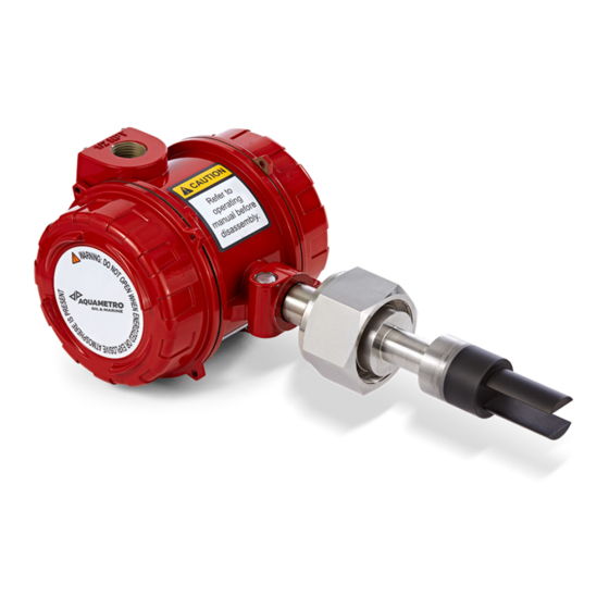
- Page 1 Version: VD 7-425 02.2021 Installation and Operation Manual Viscosity Control System Viscomaster™ / Viscomaster™ Dynamic Fuel Viscosity System...
-
Page 2: Table Of Contents
1 Introduction ............................3 Liability Disclaimer ....................................3 Safety precautions ....................................3 Receiving and Storage Requirements ............................4 Application ............................ 4 Description of Viscomaster™ Sensor ............................4 Viscosity Sensor installation / implementation ................ 5 Planning ........................................5 3.1.1 Installation checklist ..................................6 3.1.2... -
Page 3: Introduction
All safety-, installation- and operation instruction as described in this manual must be followed. Sensors, actuators and control valves are sensitive instruments and should be treated carefully. When removing or reinstalling sensors or components from the Viscomaster System, safety instructions in the respective operating manual must be followed. -
Page 4: Receiving And Storage Requirements
2 Application The Aquametro Oil & Marine Viscomaster Sensor is built to tackle the most demanding process and marine applications in viscosity control systems. It is built for the use in fuel oil systems to achieve high accurate measurements and control of the fuel oil viscosity. -
Page 5: Viscosity Sensor Installation / Implementation
VAF or Nakakita viscosity meters 3 Viscosity Sensor installation / implementation 3.1 Planning Topics covered in this chapter: Installation checklist Best practices Power requirements Other installation considerations Recommended installations for the HFVM Perform a pre-installation meter check VCS - Viscomaster™... -
Page 6: Installation Checklist
Minimum recommended voltage: 21.6 VDC with 1000 ft of 24 AWG (300 m of 0.20 mm power-supply cable At startup, power source must provide a minimum of 0.5 A of short-term current at a minimum of 19.6 V at the power-input terminals. VCS - Viscomaster™... -
Page 7: Other Installation Considerations
Power cable recommendations for explosion-proof/flameproof meters 3.1.4 Other installation considerations Numerous external factors can affect the meter's successful operation. To ensure that your system works correctly, consider the factors covered in this section when designing your installation. VCS - Viscomaster™... - Page 8 Entrained gas, or gas pockets, can disrupt the measurement of a fluid. A brief disruption in the signal caused by transient gas pockets can be corrected in the meter configuration, but you must avoid more frequent disruptions or serious gas entrainment to ensure accurate and reliable fluid measurement. VCS - Viscomaster™...
- Page 9 If it is necessary to protect against cooling because of flow loss, you can apply electrical-trace heating. If you use electrical-trace heating, use a thermostat that operates below the minimum operating temperature of the system. VCS - Viscomaster™...
- Page 10 Flow-through chamber Flow rate (0.6 to 20 m /hr) (2.6 to 87 US gal./min) Viscosity Up to 100 cSt –50 °C to 200 °C Temperature (–58 °F to 392 °F) Main flow pipe size 50 mm (2 in) VCS - Viscomaster™...
- Page 11 –50 °C to 200 °C Temperature (–58 °F to 392 °F) Defined by capillary meter Main flow pipe size chamber The AM Viscomaster is not The fork should be fully inserted calibrated for direct Placement into the main flow path up to the insertion weld bead Velocity <...
-
Page 12: Perform A Pre-Installation Meter Check
If the meter passes the test, then it has not drifted or changed during shipment. 3.2 Mounting Topics covered in this chapter: Prepare the installation Mount the meter Install thermal insulation Rotate the electronics on the meter (optional) Rotate the display on the transmitter (optional) VCS - Viscomaster™... -
Page 13: Prepare The Installation
To ensure that the fluid within the pocket is refreshed in a timely manner, verify that flow velocity at the pipe wall and fluid viscosity are within the limits described in this table. The thermal mass of the flanges may affect the response time of the meter to temperature changes. VCS - Viscomaster™... - Page 14 –50 °C to 200 °C (–58 °F to 392 °F) 40 to 330 l/min Flow 2.5 to 20 m 11 to 87 US gal/min Viscosity Up to 100 cSt Pressure As defined by process flanges Calibration 2.5 in Schedule 40 boundary VCS - Viscomaster™...
- Page 15 Keep all parts of your body away from the direction in which you will remove the sensor. Pressure caused by a valve failure or a poorly placed lock nut can eject the instrument from the flow chamber and cause serious injury. 6. Retrofit the meter per the following diagram. VCS - Viscomaster™...
- Page 16 Remove the lock nut if you can rock the meter in the flow chamber, and there is no serious or continuous escape of oil. 6. Retrofit the meter per the following diagram. VCS - Viscomaster™...
- Page 17 The direct insertion retrofit is not recommendable due to severe restrictions about the flow rate and calibration boundaries. For Direct Insertion Aquametro Oil & Marine does not take any responsibility for accuracy and lifetime. For direct insertion, no adapter is available. VCS - Viscomaster™...
-
Page 18: Rotate The Electronics On The Meter (Optional)
3. Secure the cap screw in place and tighten to 60 lb·in (6.8 N·m). 3.2.4 Rotate the display on the transmitter (optional) The display on the transmitter electronics module can be rotated 90° or 180° from the original position. VCS - Viscomaster™... -
Page 19: Wiring
If you will configure the meter to poll an external temperature or pressure device, you must wire the mA output to support HART communications. You may use either HART/mA single- loop wiring or HART multi-drop wiring. VCS - Viscomaster™... -
Page 20: Wire Power And Outputs In Signal Device And Modbus Environment
3.3.2 Wire power and outputs in Signal device and Modbus Environment CAUTION Meter installation and wiring should be performed by suitably trained personnel only, in accordance with the applicable code of practice. Procedure Wire to the appropriate power and output terminals and pins (see Figure 3-2). VCS - Viscomaster™... -
Page 21: Grounding
If the joints in the pipeline or tank are ground-bonded, the meter is automatically grounded and no further action is necessary (unless required by local code). If the joints in the pipeline or tank are not grounded, connect a ground wire to the grounding screw located on the meter electronics. VCS - Viscomaster™... -
Page 22: Viscomaster Operation
4 Viscomaster Operation Default values Default values for your meter are configured at the factory. The specific values are determined by the options that were specified on the purchase order. These are provided on the configuration sheet that was shipped with your meter. -
Page 23: Configure Modbus Communication
The setting of this parameter controls the range of valid Modbus addresses for your device. Integrate the meter with the control system Modbus ASCII support Available Modbus addresses Enabled 1–15, 32–47, 64–79, and 96–110 Disabled 1–127, excluding 111 (111 is reserved to the service port) VCS - Viscomaster™... - Page 24 The value specified here will be added to each response the device sends to the host. Default: 0 Range: 0 to 255 Do not set Additional Communications Response Delay unless required by your Modbus host. VCS - Viscomaster™...
-
Page 25: Maintenance And Repair
5 Maintenance and Repair 5.1 Calibration All our Viscomaster Systems are calibrated in the factory. An accuracy check and recalibration is offered at Aquametro Oil & Marine, this is usually dependent on customer, operator or regulation requirements. This interval depends largely on the operating conditions, process liquid and the application the system is installed in. - Page 26 Cleaning of Viscomaster do not use any aggressive solvents rinse hydraulic part of flow meter thoroughly Aquametro Oil & Marine recommends to use the following cleaning solvents: Gasoline used for cleaning purposes Cleaner’s naphtha...
-
Page 27: Spare Parts
5.3 Spare Parts Use of wrong Spare Parts Risk of malfunction or damage! Use only original spare parts, supplied by Aquametro Oil & Marine Spare part list and Maintenance instruction may be requested from Aquametro Oil & Marine. VCS - Viscomaster™... -
Page 28: Troubleshooting
Possible causes Recommended actions Erratic density Normal process noise Check your process conditions. reading Two-phase flow Increase the density damping value. Flow rate too high Reduce the flow rate. Deposition on the tines Check for two-phase flow. VCS - Viscomaster™... - Page 29 Sensor leaking heat there is no problem. If the process temperature measurement is temperature outside the specification, contact Aquametro Oil & Marine The temperature of the fluid may be changing rapidly. Allow sufficient VCS - Viscomaster™...
- Page 30 Verify that the mA output load at lower current, high resistance is below the maximum but incorrect at supported load (see the installation higher current manual for your transmitter). VCS - Viscomaster™...
-
Page 31: Decommissioning, Dismantling And Disposal
Aquametro Oil & Marine, equipment must be returned in the impurified state. In this case also the contact person at Aquametro Oil & Marine, which has granted the approval to return a crude device must be stated. VCS - Viscomaster™... -
Page 32: Disposal
Viscosity mA1+ 4mA = 0cSt - 20mA = 50cSt Dynamic Temperature mA2+ 4mA = 0°C - 20mA = 200°C Density mA1+ 4mA = 500kg/m³ - 20mA = 1500kg/m³ Density Temperature mA2+ 4mA = 0°C - 20mA = 200°C VCS - Viscomaster™... -
Page 33: Dimensional Drawings
8.2 Dimensional drawings Detailed dimensional drawing is made in project drawings. VCS - Viscomaster™... -
Page 34: Electrical Connection Diagrams
8.3 Electrical Connection diagrams Detailed connection diagram is made in project drawings. For connection with active power supply via controller, sensor passive. VCS - Viscomaster™... - Page 35 VCS - Viscomaster™...
- Page 36 VCS - Viscomaster™...
- Page 37 For connection with external power supply controller and sensor passive. VCS - Viscomaster™...
- Page 38 VCS - Viscomaster™...
- Page 39 VCS - Viscomaster™...
-
Page 40: Appendix
The optical switch indicator lights up when the transmitter senses that an optical switch has been activated. Optical switch indicator State of optical switches Solid red One optical switch is activated. Flashing red Both optical switches are activated. VCS - Viscomaster™... -
Page 41: Access And Use The Display Menu System
6. To exit the display menu system, you can use either of the following methods: Exit each menu separately, working your way back to the top of the menu system. Wait until the display times out and returns to displaying process variable data VCS - Viscomaster™... -
Page 42: Display Operation
Status Alert Severity set to Ignore. Prerequisites Operator access to the alert menu must be enabled (default setting). If operator access to the alert menu is disabled, you must use another method to view or acknowledge status alerts. VCS - Viscomaster™... - Page 43 Table 5-1: Status alerts and Status Alert Severity Default User can reset Alert number Alert title severity severity A001 EEPROM Error Fault A002 RAM Error Fault A003 No Sensor Response Fault A004 Temperature Overrange Fault A006 Characterization Required Fault VCS - Viscomaster™...
- Page 44 Output 2 Fixed Informational Ignore only Informational A115 No External Input or Polled Data Informational Ignore only Temperature Overrange (API A116 Informational Referral) A117 Density Overrange (API Referral) Informational A118 Discrete Output 1 Fixed Informational Informational VCS - Viscomaster™...
-
Page 45: You Can Control The Process Variables Shown On The Display And A Variety Of Display Behaviors
OFF-LINE MAINT > OFF-LINE CONFG > DISPLAY > ACK 9.3 Display codes and abbreviations Code Definition Units Standard DENS Line Density kg/m³ TEMP Line Temperature °Celsius; °Fahrenheit; °Kelvin EXT T Line Temperature (External) °Celsius; °Fahrenheit; °Kelvin DGAIN Drive Gain User-Defined Calculation UCALC Output VCS - Viscomaster™... - Page 46 Alert APPLY Apply AUTO Auto AUTOSCRL Auto Scroll Average DISBL Disabled DISPLAY Display DSPLY Display ENABL Enabled ENTER Enter EXIT Exit OFFSET Offset Out of range PASSW Password or passcode RESTORE Restore RESULT Result RTEMP Reference temperature VCS - Viscomaster™...
- Page 47 VCS - Viscomaster™...
- Page 48 Aquametro Oil & Marine AG Aquametro Oil & Marine GmbH CH-4106 Therwil, Switzerland DE-18119 Rostock, Germany info@aquametro-oil-marine.com info@aquametro-oil-marine.com www.aquametro-oil-marine.com Phone +41 61 725 44 00 Phone +49 381 382 530 00 VCS - Viscomaster™...
Need help?
Do you have a question about the Viscomaster and is the answer not in the manual?
Questions and answers