Advertisement
Table of Contents
- 1 Required Tools
- 2 Supplied Parts and Hardware
- 3 Step 1: Mount the Wall Plate: Wood Stud Installation Only
- 4 Step 2: Add Arm Assembly to a Television with a Flat Back
- 5 Step 4: Hang Arm Assembly on Wall Plate
- 6 Step 5: Add Safety Bolts
- 7 Step 6: Leveling and Adjusting Tension on the Monitor
- 8 Step 7: Cable/Wire Management
- Download this manual
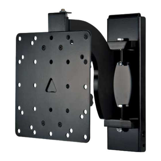
Thank you for choosing a Sanus Systems VisionMount™ wall mount. The MF110 is designed to mount LCD flat panels with VESA (Video
Electronics Standards Association) hole pattern up to 200mm x 200mm and weighing up to 100 lb [45.5 Kg] to a vertical wall. It will allow the
television to be pulled out 9.5" [241.3 mm] from of the wall. It will allow you to swivel the television ±30° (may vary with size of television), tilt +5°
to -15°, and have a ±6° roll control.
CAUTION: The size and weight of your television must not exceed 100 Lbs [45.5 Kg]. The wall must be capable of supporting five
times the weight of the television plus the wall mount. Never use defective parts. Improper installation may cause property damage or
personal injury. Do not use this product for any purpose that is not explicitly specified by Sanus Systems.
If you do not understand these directions, or have any doubts about the safety of the installation, please call a qualified contractor or contact
Sanus at 800.359.5520 or www.sanus.com. Our customer service representatives can quickly assist you with installation questions and missing
or damaged parts. Replacement parts for products purchased through authorized dealers will be shipped directly to you. Check carefully to make
sure that there are no missing or defective parts. Sanus Systems can not be liable for damage or injury caused by incorrect mounting, incorrect
assembly, or incorrect use. Please call Sanus Systems before returning products to the point of purchase.
NOTE: This mount is not intended for use on brick, concrete block, concrete, or steel wall studs. Typical wall anchors do not have
sufficient holding power to support this mount. It is up to the installer to verify the safety of any installation method or hardware that is
not provided by or recommended by Sanus Systems. Sanus Systems makes every effort to assure all necessary television mounting
hardware is included. If the television mounting hardware you need is not included please consult your local hardware store or call
Sanus Systems.
Required Tools: Drill, 3/16" drill bit, wrench set, Philips screwdriver
Supplied Parts and Hardware: (Some parts are not shown at the same scale)
M4 x 12 mm Bolt - C
Qty .4
M4 x 30 mm Bolt - F
Qty .4
M4 Lock Washer - I
Qty .4
Sanus Systems
Customer Service: 800.359.5520. See complementary Sanus products at www.sanus.com
Assembly Instructions for Model: MF110
Wall Plate - A
Qty .1
M5 x 12 mm Bolt - D
M5 x 30 mm Bolt - G
M5 Lock Washer - J
2221 Hwy 36 West, Saint Paul, MN 55113 10.11.06 (6901-100044)
Arm Assembly - B
Qty .1
Qty .4
Qty .4
Qty .4
M6 x 12 mm Bolt - E
Qty .4
M6 x 35 mm Bolt - H
Qty .4
M6 Lock Washer - K
Qty .4
Advertisement
Table of Contents

Subscribe to Our Youtube Channel
Related Manuals for Sanus VisionMount MF110


Summary of Contents for Sanus VisionMount MF110
- Page 1 Replacement parts for products purchased through authorized dealers will be shipped directly to you. Check carefully to make sure that there are no missing or defective parts. Sanus Systems can not be liable for damage or injury caused by incorrect mounting, incorrect assembly, or incorrect use.
- Page 2 M4/M5 Spacer - L M6 Spacer - M M4/M5 Washer - N Qty. 4 Qty. 4 Qty. 4 Lag Bolt - P Lag Bolt Wsher - Q M6 Washer - O Qty. 3 Qty. 3 Qty. 4 Safety Bolt - S Qty.
- Page 3 Step 2: Add Arm Assembly to a television with a flat back NOTE: If your television has a curved back, or any other obstruction, proceed directly to Step 3. First, determine the diameter of the Bolt (C,D,E) your TV requires by hand threading them into the threaded insert on the back of the TV. If you encounter any resistance stop immediately! Once you have determined the correct diameter, see the appropriate Diagram below.
- Page 4 Step 3: Add Arm Assembly to a television with a curved back, recessed area around the threaded inserts or any other obstruc- tion. First, determine the diameter of the Bolt (F,G,H) your TV requires by hand threading them into the threaded insert on the back of the TV. If you encounter any resistance stop immediately! Once you have determined the correct diameter, see the appropriate Diagram below.
- Page 5 Step 4: Hang Arm Assembly on Wall Plate Diagram 4 CAUTION: This step may require two people to lift the assembly onto the Wall Plate. Sanus Systems is not responsible for property damage and/or per- sonal injury. Wall Transfer Orient the Arm Assembly (B) so that the arm extends directly away from the Bracket television and the transfer bracket is parallel with the television.
- Page 6 Step 6: Leveling and Adjusting Tension on the Monitor CAUTION: Do not remove the Tension Nuts labeled in Diagram 6a. Removing Tension Nuts may result in property damage. Once the television is mounted onto the Wall Plate (A), and the Safety Bolts (S) are tight, it can be adjusted to level. Slightly loosen the two Allen Bolts on the back of the Arm Assembly (B).
Need help?
Do you have a question about the VisionMount MF110 and is the answer not in the manual?
Questions and answers