Advertisement
Available languages
Available languages
Quick Links
Advertisement

Subscribe to Our Youtube Channel
Related Manuals for SCULPFUN S6


Summary of Contents for SCULPFUN S6
- Page 1 English Deutsche Français Italiano Español Polskie...
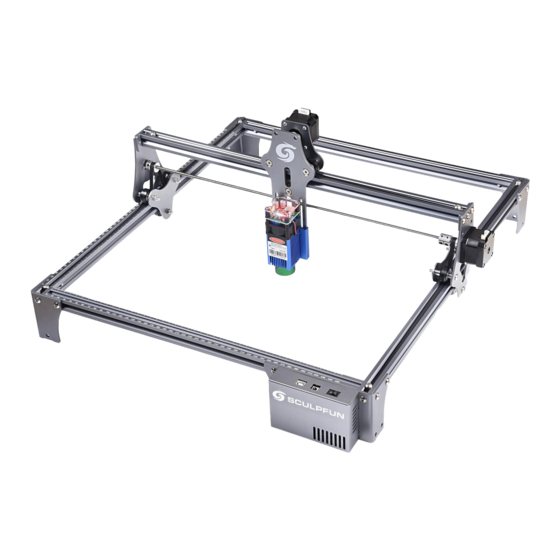
- Page 2 Preview the main parts Main Unit: 1、Back Beam 1、Back Beam 7、X Beam set 2、Front Beam 3、Left Beam 4、Right Beam 5、Foot support 6、Mainboard support 7、X Beam set 3、Left Beam 8、Laser module Note! This picture is the total picture after the assembly is completed. 8、Laser module In the subsequent steps, if you are unclear about...
- Page 3 Step 1 Assemble the back, left and right beams Back Beam Back Beam Left Beam Right Beam M5*30 Note: Back Beam 1、Find the required tool and screw model before starting assembly: T- M5*18 M5*18 shaped hexagon wrench,Step1 Screw bag, left/right/back frame beams, tripod*2.
- Page 4 Step 2 Assemble X beam set and front beam Tripod Motherboard tripod Assembly steps: M5*30 1、Push the X beam assembly into the U-shaped frame, paying attention to the direction of white logo 2、Required components: tripod*1, motherboard tripod, front frame M5*18 M5*18 beam, Step3 screw pack, T-shaped hexagonal wrench.
-
Page 5: Step 3 Install The Belt
Step 3 Install the belt Installation steps: Install the belt to the position shown in the figure,note: 1. The belt should be installed in the direction of the arrow in the figure above. 2. The tooth pattern of the belt faces downwards and engages with the gears. - Page 6 Step 4 Install T nut Put the T nut into the groove, the long side is Tighten the screws and keep parallel to the groove, Strongly press the T nut the long side of the T-nut while rotating the wrench clockwise to make the perpendicular to the groove.
- Page 7 Step 5 Install laser module and data cable Laser If the tightness of the roller and the guide rail is not suitable, use a wrench to turn it up and down to control the tightness of the roller and the guide rail Question: How to judge the tightness of the belt? Answer: After the installation is completed, tilt Data Cable...
- Page 8 The focusing principle of SCULPFUN laser module measuring edge of the aluminum aluminum Focusing principle: column alloy shell 1、The focal length of the SCULPFUN laser module is fixed and cannot be changed . 2、The specific position of the laser 20mm...
- Page 9 How to quickly focus laser on the surface of the sculpture 20mm 1、Place the measuring 2、When the laser module is 3、After fixing the laser aluminum column on the in good contact with the module, remove the surface of the engraved measuring aluminum column, measuring aluminum column object, loosen the...
- Page 10 Manufacturer: Shenzhen Sculpfun Technology Co., Ltd. Address: 1411, Building D, Longguang Jiuzuan Business Center South, Daling Community, Minzhi Street, Longhua District, Shenzhen, Guangdong, China 518131 Sculp your fun ! Note:This Manual is just for installation, For how to use laserGRBL software, how to show the position of...
- Page 11 English Deutsche Français Italiano Español Polskie...
- Page 12 Vorschau der Hauptteile Haupteinheit: 1 、 Rückstrahl 2 、 Frontbalken 1、Back Beam 7、X Strahlensatz 3 、 Linker Strahl 4 、 Rechter Strahl 5 、 Fußstütze 6 、 Mainboard- Unterstützung 7 、 X Strahlensatz 8 、 Lasermodul Hinweis! 3、Left Beam Dieses Bild ist das Gesamtbild nach Abschluss der Montage.
- Page 13 Schritt 1 Montieren Sie den hinteren, linken und rechten Balken Back Beam Back Beam Left Beam Right Beam M5*30 Hinweis: Back Beam 1 、 Suchen Sie das gewünschte Werkzeug- und Schraubenmodell, bevor Sie mit M5*18 M5*18 der Montage beginnen: T-förmiger Sechskantschlüssel, Schritt 1 Schraubbeutel, Rahmenbalken links / rechts / hinten, Stativ * 2.
- Page 14 Schritt 2 Montieren Sie den X-Balkensatz und den vorderen Balken Stativ Motherboard- Stativ Montageschritte: 1 、 Schieben Sie die X-Trägerbaugruppe in den U-förmigen Rahmen und achten Sie dabei auf die Richtung des weißen Logos! M5*30 2 、 Erforderliche Komponenten: Stativ * 1, Motherboard-Stativ, Frontrahmenbalken, Step3-Schraubensatz, T-förmiger M5*18 M5*18...
- Page 15 Schritt 3 Installieren Sie den Riemen Installation steps: Install the belt to the position shown in the figure,note: 1. The belt should be installed in the direction of the arrow in the figure above. 2. The tooth pattern of the belt faces downwards and engages with the gears.
- Page 16 Schritt 4 Installieren Sie die T-Mutter Setzen Sie die T-Mutter in die Nut ein. Die lange Ziehen Sie die Schrauben an Seite verläuft parallel zur Nut. Drücken Sie die T- und halten Sie die lange Seite Mutter fest, während Sie den Schraubenschlüssel der T-Mutter senkrecht zur Nut.
- Page 17 Schritt 5 Installieren Sie das Lasermodul und das Datenkabel Laser Wenn die Dichtheit der Rolle und der Führungsschiene nicht geeignet ist, drehen Sie sie mit einem Schraubenschlüssel auf und ab, um die Dichtheit der Rolle und der Führungsschiene zu kontrollieren Frage: Wie kann man die Enge des Gürtels beurteilen? Datenkabel...
- Page 18 Das Fokussierungsprinzip des SCULPFUN-Lasermoduls Messsäule aus Kante der Aluminium Aluminiumlegierungsschale Fokussierungsprinzip: 1 、 Die Brennweite des SCULPFUN- Lasermoduls ist fest und kann nicht geändert werden. 2 、 Die spezifische Position des 20mm 20mm Laserfokus liegt 20 mm direkt unter der Kante der Aluminiumlegierungshülle des...
- Page 19 So fokussieren Sie den Laser schnell auf die Oberfläche der Skulptur 20mm 1 、 Platzieren Sie die 2 、 Wenn das Lasermodul 3 、 Entfernen Sie nach dem Messaluminiumsäule auf der guten Kontakt mit der Befestigen des Lasermoduls Oberfläche des gravierten Messaluminiumsäule hat, die Messaluminiumsäule und Objekts, lösen Sie die...
- Page 20 Hersteller: Shenzhen Sculpfun Technology Co., Ltd. Adresse: 1411, Gebäude D, Longguang Jiuzuan Business Center Süd, Daling-Gemeinde, Minzhi-Straße, Bezirk Longhua, Shenzhen, Guangdong, China 518131 Sculp your fun ! Hinweis: Dieses Handbuch dient nur zur Installation. Informationen zur Verwendung der laserGRBL- Software, zur Anzeige der Position des Gravurmusters...
- Page 21 English Deutsche Français Italiano Español Polskie...
- Page 22 Aperçu des pièces principales Unité principale: 1、Back Beam 1, poutre arrière 2, poutre avant 3, faisceau gauche 4, faisceau droit 7、Ensemble de 5, support de pied poutres en X 6, prise en charge de la carte mère 7, ensemble de poutres X 8, module laser 3、Left Beam Noter! Cette image est...
- Page 23 Étape 1 Assemblez les poutres arrière, gauche et droite Back Beam Back Beam Left Beam Right Beam M5*30 Noter: Back Beam 1, trouvez l'outil requis et le modèle de vis avant de commencer M5*18 M5*18 l'assemblage: clé hexagonale en forme de T, sac de vis Step1, poutres de cadre gauche / droite / arrière, trépied * 2.
- Page 24 Étape 2 Assemblez l'ensemble de poutre X et la poutre avant Trépied Trépied de la carte mère Étapes d'assemblage : M5*30 1, poussez l'ensemble de poutre X dans le cadre en forme de U, faisant attention à la direction du logo blanc! 2, composants requis: trépied * 1, trépied de carte mère, poutre de M5*18 M5*18...
- Page 25 Étape 3 Installez la courroie Etapes d'installation: Installez la courroie dans la position indiquée sur la figure, notez: 1. La courroie doit être installée dans le sens de la flèche sur la figure ci- dessus. 2. La denture de la courroie est tournée vers le bas et s'engage avec les engrenages.
-
Page 26: Etapes D'installation
Étape 4 Installez l'écrou en T Mettez l'écrou en T dans la rainure, le côté long Serrez les vis et maintenez le est parallèle à la rainure, appuyez fortement sur côté long de l'écrou en T l'écrou en T tout en tournant la clé dans le sens perpendiculaire à... - Page 27 Étape 5 Installez le module laser et le câble de données Laser Si l'étanchéité du rouleau et du rail de guidage ne convient pas, utilisez une clé pour le tourner de haut en bas pour contrôler l'étanchéité du rouleau et du rail de guidage Question: Comment juger de l'étanchéité...
- Page 28 Le principe de focalisation du module laser SCULPFUN mesure de la bord de la colonne en aluminium Principe de mise au point: aluminium coque en alliage 1, la distance focale du module laser SCULPFUN est fixe et ne peut pas être modifiée.
- Page 29 Comment focaliser rapidement le laser sur la surface de la sculpture 20mm 1、 placez la colonne en 2、 lorsque le module laser est 3、après avoir fixé le module aluminium de mesure sur la en bon contact avec la colonne laser, retirez la colonne en surface de l'objet gravé, en aluminium de mesure, aluminium de mesure et...
-
Page 30: Service Clients
Fabricant: Shenzhen Sculpfun Technology Co., Ltd. Adresse: 1411, bâtiment D, centre d'affaires de Longguang Jiuzuan sud, communauté de Daling, rue Minzhi, district de Longhua, Shenzhen, Guangdong, Chine 518131 Sculp your fun ! Remarque : Ce manuel est juste pour l'installation,... - Page 31 English Deutsche Français Italiano Español Polskie...
- Page 32 Visualizza in anteprima le parti principali Unità principale: 1 、 Trave posteriore 1、Back Beam 2 、 fascio anteriore 3、raggio sinistro 7、X Beam set 4、 raggio destro 5 、 Poggiapiedi 6 、 Supporto per scheda madre 7 、 X Beam set 3、Left Beam 8、...
- Page 33 Passaggio 1 Assemblare le travi posteriore, sinistra e destra Back Beam Back Beam Left Beam Right Beam M5*30 Nota: Back Beam 1 、 Trovare lo strumento e il modello di vite richiesti prima di iniziare il montaggio: chiave esagonale a forma di T, borsa per viti Step1, travi del M5*18...
- Page 34 Passaggio 2 Assemblare il set di travi X e la trave anteriore Treppiedi Treppiede per scheda madre Fasi di montaggio : M5*30 1 、 Spingere il gruppo del raggio X nel telaio a forma di U, prestando attenzione alla direzione del logo bianco! 2, componenti necessari: treppiede * 1, treppiede della scheda madre, M5*18 M5*18...
- Page 35 Passaggio 3 Installare la cintura Fasi di installazione: Installare la cinghia nella posizione mostrata in figura, nota: 1. La cinghia deve essere installata nella direzione della freccia nella figura sopra 2. La configurazione dei denti della cinghia è rivolta verso il basso e si innesta con gli ingranaggi.
- Page 36 Passaggio 4 Installare il dado a T. Mettere il dado a T nella scanalatura, il lato lungo Stringere le viti e mantenere il è parallelo alla scanalatura, premere con forza il lato lungo del dado a T dado a T mentre si ruota la chiave in senso orario perpendicolare alla scanalatura.
- Page 37 Passaggio 5 Installare il modulo laser e il cavo dati Laser Se la tenuta del rullo e del binario di guida non è adatta, utilizzare una chiave per ruotarlo su e giù per controllare la tenuta del rullo e del binario di guida Domanda: come giudicare la tenuta della Cavo dati cintura?
- Page 38 Il principio di focalizzazione del modulo laser SCULPFUN misurazione bordo del alluminio alluminio Principio di messa a fuoco: colonna guscio in lega 1 、 La lunghezza focale del modulo laser SCULPFUN è fissa e non può essere modificata. 2 、 La posizione specifica del fuoco laser è...
- Page 39 Come mettere rapidamente a fuoco il laser sulla superficie della scultura 20mm 1 、 Posizionare la colonna di 2 、 Quando il modulo laser è 3 、 Dopo aver fissato il misurazione in alluminio sulla in buon contatto con la modulo laser, rimuovere la superficie dell'oggetto inciso, colonna di misurazione in...
-
Page 40: Assistenza Clienti
Produttore: Shenzhen Sculpfun Technology Co., Ltd. Indirizzo: 1411, Building D, Longguang Jiuzuan Business Center South, Daling Community, Minzhi Street, Longhua District, Shenzhen, Guangdong, China 518131 Sculp your fun ! Nota : Questo manuale è solo per l'installazione, per come utilizzare il software laserGRBL, come mostrare... - Page 41 English Deutsche Français Italiano Español Polskie...
- Page 42 Vista previa de las partes principales Unidad principal: 1, haz trasero 1、Back Beam 2, haz delantero 3, haz izquierdo 4, haz derecho 7、Conjunto de 5, Soporte para pies vigas X 6, soporte de placa base 7, X Beam conjunto 8 , módulo láser 3、Left Beam ¡Nota! Esta imagen es la imagen total después...
- Page 43 Paso 1 Ensamble las vigas traseras, izquierda y derecha Back Beam Back Beam Left Beam Right Beam M5*30 Nota: Back Beam 1 、 Encuentre la herramienta requerida y el modelo de tornillo antes de M5*18 M5*18 comenzar el ensamblaje: llave hexagonal en forma de T, bolsa de tornillo Step1, vigas del marco izquierdo / derecho / trasero, trípode * 2.
- Page 44 Paso 2 Ensamble el conjunto de vigas X y la viga delantera Trípode Trípode de placa base Pasos de montaje: M5*30 1 、 Empuje el conjunto de la viga X en el marco en forma de U, prestando atención a la dirección del logotipo blanco. 2 、...
- Page 45 Paso 3 Instale la correa Pasos de instalación: Instale la correa en la posición que se muestra en la figura, tenga en cuenta: 1. La correa debe instalarse en la dirección de la flecha en la figura anterior. 2. El patrón dentado de la correa mira hacia abajo y se acopla con los engranajes.
- Page 46 Paso 4 Instale la tuerca en T Coloque la tuerca en T en la ranura, el lado largo Apriete los tornillos y es paralelo a la ranura, presione con fuerza la mantenga el lado largo de la tuerca en T mientras gira la llave en el sentido de tuerca en T perpendicular a la las agujas del reloj para hacer que el lado largo de ranura.
- Page 47 Paso 5 Instale el módulo láser y el cable de datos Laser Si el apriete del rodillo y el riel de guía no es adecuado, use una llave para girarlo hacia arriba y hacia abajo para controlar el apriete del rodillo y el riel de guía Pregunta: ¿Cómo juzgar la tensión del cinturón? Cable de Respuesta: Una vez completada la instalación,...
- Page 48 El principio de enfoque del módulo láser SCULPFUN medición borde de la aluminio aluminio Principio de enfoque: columna carcasa de aleación 1 、 La distancia focal del módulo láser SCULPFUN es fija y no se puede cambiar. 2 、 La posición específica del...
- Page 49 Cómo enfocar rápidamente el láser en la superficie de la escultura 20mm 1 、 Coloque la columna de 2 、 Cuando el módulo láser 3 、 Después de fijar el aluminio de medición en la esté en buen contacto con la módulo láser, retire la superficie del objeto grabado, columna de aluminio de...
- Page 50 Fabricante: Shenzhen Sculpfun Technology Co., Ltd. Dirección: 1411, Edificio D, Centro de negocios Longguang Jiuzuan Sur, Comunidad Daling, Calle Minzhi, Distrito Longhua, Shenzhen, Guangdong, China 518131 Sculp your fun ! Nota: Este manual es solo para la instalación. Para saber cómo usar el software laserGRBL, cómo mostrar la posición del patrón de grabado y cómo configurar...
- Page 51 English Deutsche Français Italiano Español Polskie...
- Page 52 Wyświetl podgląd głównych części Jednostka główna: 1、Back Beam 1, tylna belka 2, przednia belka 7、X Beam set 3, lewa belka 4, prawa belka 5, podpórka pod stopy 6, wsparcie płyty głównej 3、Left Beam 7, X zestaw belek 8, moduł laserowy Uwaga! To zdjęcie jest całkowitym obrazem po zakończeniu montażu.
- Page 53 Krok 1 Zmontuj tylną, lewą i prawą belkę Back Beam Back Beam Left Beam Right Beam Uwaga: M5*30 Back Beam 1, Znajdź wymagane narzędzie i model śruby przed rozpoczęciem montażu: klucz sześciokątny w kształcie litery T, Step1 Torba na śruby, M5*18 M5*18 belki ramy lewa / prawa / tylna, statyw * 2.
- Page 54 Krok 2 Zmontuj zestaw belek X i belkę przednią Statyw Statyw do płyty głównej Etapy montażu : M5*30 1 、 Wepchnij zespół belki X do ramy w kształcie litery U, zwracając uwagę na kierunek białego logo! 2, Wymagane komponenty: statyw * 1, statyw płyty głównej, belka M5*18 M5*18 ramy przedniej, pakiet śrub Step3, klucz sześciokątny w kształcie litery...
- Page 55 Krok 3 Załóż pasek Kroki instalacji: Zamontuj pasek w pozycji pokazanej na rysunku, zwróć uwagę: 1. Pas należy zamontować w kierunku wskazanym przez strzałkę na powyższym rysunku. 2. Ząbki paska są skierowane w dół i zazębiają się z kołami zębatymi. 3.
- Page 56 Krok 4 Zainstaluj nakrętkę T Umieść nakrętkę T w rowku, długi bok jest Dokręć śruby i utrzymuj długi równoległy do rowka, mocno naciśnij nakrętkę T, bok nakrętki młoteczkowej jednocześnie obracając klucz zgodnie z ruchem prostopadle do rowka. wskazówek zegara, aby długi bok nakrętki T był prostopadły do rowka Kroki instalacji: 1.
- Page 57 Krok 5 Zainstaluj moduł laserowy i kabel do transmisji danych Laser Jeśli szczelność rolki i szyny prowadzącej nie jest odpowiednia, użyj klucza, aby obrócić ją w górę iw dół, aby kontrolować szczelność rolki i szyny prowadzącej Pytanie: Jak ocenić szczelność paska? Odpowiedź: Po zakończeniu instalacji przechyl Kabel do transmisji maszynę...
- Page 58 Zasada skupienia: kolumna skorupa ze stopu 1, Ogniskowa modułu laserowego SCULPFUN jest stała i nie można jej zmienić. 2, specyficzna pozycja ogniska lasera 20mm 20mm znajduje się 20 mm bezpośrednio pod krawędzią powłoki ze stopu aluminium modułu laserowego.
- Page 59 Jak szybko skupić laser na powierzchni rzeźby 20mm 1, umieść aluminiową 2, gdy moduł laserowy ma 3 、 Po zamocowaniu kolumnę pomiarową na dobry kontakt z aluminiową modułu laserowego wyjmij powierzchni grawerowanego kolumną pomiarową, dokręć aluminiową kolumnę przedmiotu, poluzuj śrubę śrubę...
- Page 60 Technology Producent: Shenzhen Sculpfun Co., Ltd. Adres: 1411, budynek D, Longguang Jiuzuan Business Centre South, Daling Community, Minzhi Street, Longhua District, Shenzhen, Guangdong, Chiny 518131 Sculp your fun ! Uwaga : Niniejsza instrukcja służy tylko do instalacji. Aby dowiedzieć się, jak korzystać z oprogramowania laserGRBL, jak pokazać...
Need help?
Do you have a question about the S6 and is the answer not in the manual?
Questions and answers