Table of Contents
Advertisement
Available languages
Available languages
Quick Links
Advertisement
Table of Contents

Related Manuals for Konig & Meyer 23878


Summary of Contents for Konig & Meyer 23878
- Page 1 23878 Bildschirm‑ Dreifachhalter VESA Load 15” - 24” 0-8kgs/0-17.6lbs 75x75, 100x100 KÖNIG & MEYER GmbH & Co. KG Kiesweg 2, 97877 Wertheim, www.k-m.de 23878-000-55 Rev.01 3/22 -90°/+85° 180° 360° Neigung Schwenkbar Drehbar Montage ANL E I T UN G...
- Page 2 WARNHINWEISE Warnung Vor der Installation dieses Produkts muss die Installationsanleitung vollständig gelesen werden. Bei Nichtbeachtung kann es zu Personen- und Sachschäden oder zum Erlöschen der Garantie kommen. Installieren Sie den Halter nicht an einer Stelle, an der er Vibrationen, Bewegungen oder Stößen ausgesetzt ist. Falls erforderlich, verstärken Sie die Tischplatte vor der Installation.
- Page 3 BENÖTIGTE WERKZEUGE (nicht im Lieferunfang) LIEFERUMFANG (x2) (x2) (x1) M4x12 (x12) M4x30 (x12) 12X5.8X16 (x12) (x2) M6x25 (x4) (x4) S=3mm (x1) S=5mm (x1) (x1)
- Page 4 Installation der Klammer ① ② S=3mm S=5mm Schreibtisch Messen Sie die Stärke der Tischplatte ③ ④ S=3mm Schreibtisch Bei einer Tischdicke von mehr als 60 mm (2,36") und höchstens 85 mm (3,35"), entfernen Sie die Klemmschraube von der unteren Aufnahme und bringen diese um 180°...
- Page 5 Installation des Arms S=3mm S=3mm Stellen Sie den Anschlagring auf die gewünschte Höhe ein und schrauben Sie ihn fest. Stecken Sie die Halterung in das Stahlrohr oberhalb des Fixierrings. M6x25 Führen Sie die Schraube durch die Bohrungen der Halterung in Richtung der Abdeckkappen.
-
Page 6: Installation Des Monitors
Installation des Monitors M4x12 M4x30 12X5.8X16 M4x12 M4x30 ODER M4x30 M4x12 ODER Bündige Montage: Montieren Sie die VESA-Halterung mit den 4 Schrauben am Monitor. Abgesetzte Montage: Legen Sie die 4 Abstandshalter zwischen die VESA- Halterung und den Monitor. Montieren Sie die VESA-Halterung, mit den 4 Schrauben durch die Abstandshalter am Monitor. - Page 7 M6x25 Führen Sie die Schraube durch die Bohrungen des Verlängerungsarme in Richtung der Abdeckkappen. Heben Sie die VESA-Platten zusammen mit dem Monitoren an und setzen Sie diese auf die Halterung. Einstellen der Spannung der Gasdruckfeder Drücken Sie den Arm nach unten in die horizontale Position Achten Sie darauf, dass der Arm während der Einstellung in horizontaler Position bleibt.
- Page 8 Neigungs- und Schwenkverstellung VESA Neigungseinstellung VESA Schwenkeinstellung S=3mm S=5mm S=5mm S=5mm Arm Schwenk- einstellung S=3mm Verwenden Sie einen Innensechskantschlüssel, zur Einstellung der Beweglichkeit. Drehen Sie gegen den Uhrzeigersinn, um sie zu verringern und im Uhrzeigersinn, um sie zu erhöhen. Führen Sie die Kabel in die Kabelabdeckungen ein. Verwenden Sie die Kabelklemme, um die Kabel am Grundrohr zu befestigen.
-
Page 9: Installation
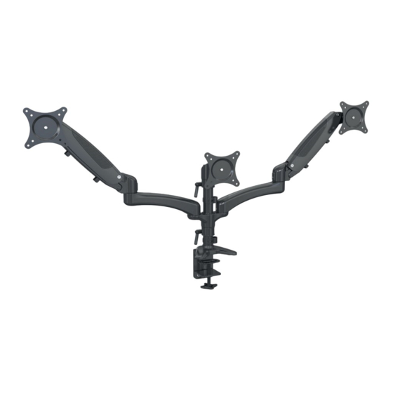
23878 Triple monitor mount VESA Load 15” - 24” 0-8kgs/0-17.6lbs 75x75, 100x100 Tilt Rotate KÖNIG & MEYER GmbH & Co. KG Swivel Kiesweg 2, 97877 Wertheim, www.k-m.de 23878-000-55 Rev.01 3/22 -90°/+85° 180° 360° Installation INSTRUCTIONS... -
Page 10: Warning Statements
WARNING STATEMENTS Warning Prior to the installation of this product, the installation instruction must be read and completely understood. Failure to do so may result in personal injury, property damage or voiding of factory warranty. Do not install on a structure that is prone to vibration, movement or chance of impact. -
Page 11: Parts Included
TOOLS REQUIRED NOT INCLUDED PARTS INCLUDED (x2) (x2) (x1) M4x12 (x12) M4x30 (x12) 12X5.8X16 (x12) (x2) M6x25 (x4) (x4) S=3mm (x1) S=5mm (x1) (x1) - Page 12 Clamp Installation Steps ① ② S=3mm S=5mm Desktop Measure the thickness of desktop ③ ④ S=3mm Desktop For desk thickness more than 2.36"(60 mm) but within 3.35"(85 mm), remove clamp screw and attachment entirely and reattach clamp screw with bottom plate upside-down.
-
Page 13: Arm Installation
Arm Installation S=3mm S=3mm Adjust locating ring at proper height and screw up tight to hold the mount. Insert supporting part to the steel pipe above the locating ring. M6x25 Insert the screw through the hole from supporting part to the decorative cap. Insert steel fastener to the steel pipe. -
Page 14: Monitor Installation
Monitor Installation M4x12 M4x30 12X5.8X16 M4x12 M4x30 M4x30 M4x12 Flush surface installation: Install 4 screws through faceplate to monitor via mounting holes. Recessed surface installation: Put 4 spacers between faceplate and monitor. Install 4 screws through faceplate, spacers to monitor via mounting holes. - Page 15 M6x25 Insert the screw through the hole from extension arm to the decorative cap. Lift the VESA plate along with monitor and put it on head slot. Gas Spring Tension Adjustment Press down the arm to a horizontal position S=5mm 1 turn ≈...
-
Page 16: Cable Management Installation
Tilt & Swivel Adjustment VESA Tilt Adjustment VESA Swivel Adjustment S=3mm S=5mm S=5mm S=5mm Arm Swivel Adjustment S=3mm Use a hex wrench to adjust the damp for swiveling. Turn counter-clockwise to reduce damping and clockwise to increase damping. Cable Management Installation Insert cables into cable covers.
Need help?
Do you have a question about the 23878 and is the answer not in the manual?
Questions and answers