Advertisement
Available languages
Available languages
Quick Links
Advertisement

Subscribe to Our Youtube Channel
Related Manuals for Konig & Meyer 23870


Summary of Contents for Konig & Meyer 23870
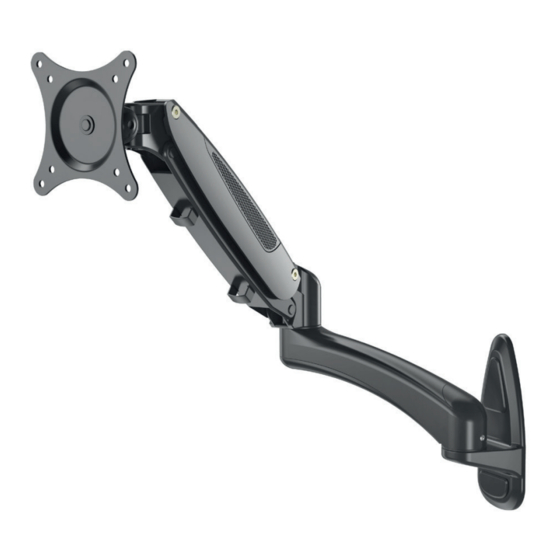
- Page 1 23870 Bildschirm- Wandhalter VESA Last 15” - 32” 0-8kgs/0-17.6lbs 75/100 KÖNIG & MEYER GmbH & Co. KG Kiesweg 2, 97877 Wertheim, www.k-m.de 23870-000-55 Rev.01 3/21 -90°/+85° 180° 360° Neigung Schwenkbar Drehbar Montage ANL E I T U N G...
- Page 2 WARNHINWEISE Warnung Vor der Installation dieses Produkts muss die Installationsanleitung vollständig gelesen werden. Bei Nichtbeachtung kann es zu Personen- und Sachschäden oder zum Erlöschen der Garantie kommen. Installieren Sie den Halter nicht an einer Stelle, an der er Vibrationen, Bewegungen oder Stößen ausgesetzt ist. Falls erforderlich, verstärken Sie die Wand vor der Installation.
- Page 4 30mm (1.2”) (0.12”) Markieren Sie die Stelle für die Montage mit einem Bleistift. Stellen Sie sicher, dass die Wandstruktur das Gewicht des Monitors zusammen mit dem Halter trägt. Nur an den Holzständern einer Gipskarton- oder Hohlwand montieren! 50mm (2.0”) (0.31”) Markieren Sie die Stelle für die Montage mit einem Bleistift.
- Page 5 Bringen Sie die beiden Kunststoffabdeckungen an. ODER Montieren Sie die VESA-Halterung mit den der 4 Schrauben am Monitor. Abgesetzte Montage: Legen Sie die 4 Abstandshalter zwischen die VESA- Halterung und den Monitor. Montieren Sie die VESA-Halterung, mit den 4 Schrauben durch die Abstandshalter am Monitor.
- Page 6 Führen Sie die Schraube durch die Bohrung der Wandplatte in Richtung der Abdeckkappe. Stecken Sie den Verlängerungsarm in die Wandplatte. Führen Sie die Schraube durch die Bohrung des Verlängerungsarms in Richtung der Abdeckkappe. Heben Sie den Federarm zusammen mit dem Monitor an und setzen Sie ihn auf den Verlängerungsarm.
- Page 7 Drücken Sie den Arm nach unten in die horizontale Position 1 Umdrehung HINWEIS: Drehen Sie im Uhrzeiger- Verwenden Sie einen Innensechskantschlüssel, um die Spannung des Gasdruckfederarms einzustellen, sodass Monitore mit unterschiedlichem Gewicht in jeder Position gehalten werden können.
- Page 8 VESA Neigungseinstellung VESA Schwenkeinstellung S=3mm Arm Schwenk- einstellung Verwenden Sie einen Innensechskantschlüssel, zur Einstellung der Beweglichkeit. Drehen Sie gegen den Uhrzeigersinn, um sie zu verringern und im Uhrzeigersinn, um sie zu erhöhen. Führen Sie die Kabel in die Kabelabdeckungen ein. Lassen Sie den Kabeln, für eine optimale Einstellung, genügend Spielraum an den Gelenken.
-
Page 9: Installation
23870 Monitor Wall Mount VESA Load 15” - 32” 0-8kgs/0-17.6lbs 75/100 Tilt Rotate KÖNIG & MEYER GmbH & Co. KG Swivel Kiesweg 2, 97877 Wertheim, www.k-m.de 23870-000-55 Rev.01 3/21 -90°/+85° 180° 360° Installation INSTRUCTIONS... -
Page 10: Warning Statements
WARNING STATEMENTS Warning Prior to the installation of this product, the installation instruction must be read and completely understood. Failure to do so may result in personal injury, property damage or voiding of factory warranty. Do not install on a structure that is prone to vibration, movement or chance of impact. -
Page 11: Parts Included
TOOLS REQUIRED NOT INCLUDED PARTS INCLUDED... - Page 12 30mm (1.2”) (0.12”) Use a pencil to mark the place for mounting. Make sure the wall structure can support the weight of monitor along with the mount. Avoid dead center for mounting holes. 50mm (2.0”) (0.31”) Use a pencil to mark the place for mounting. Make sure the wall structure can support the weight of monitor along with the mount.
- Page 13 Insert the two plastic covers on wall plate for decorative appearance. Recessed surface installation: Put 4 spacers between faceplate and monitor. Install 4 screws through faceplate, spacers to monitor via mounting holes.
- Page 14 Insert the screw through the hole from the wall plate to the decorative cap. Insert extension arm to the wall plate. Insert the screw through the hole from extension arm to the decorative cap. Lift the spring arm along with the monitor and put it on the extension arm.
- Page 15 Press down the arm to a horizontal position Use a hex wrench to adjust the height tension of the gas spring arm, to keep different weight of monitors still at any position.
- Page 16 VESA Tilt Adjustment VESA Swivel Adjustment S=3mm Arm Swivel Adjustment Use a hex wrench to adjust the damp for swiveling. Turn counter-clockwise to reduce damping and clockwise to increase damping. Insert cables into cable covers. Leave enough slack of cables at arm joints for full adjustment.
Need help?
Do you have a question about the 23870 and is the answer not in the manual?
Questions and answers