Table of Contents
Advertisement
Quick Links
;
For identification of product codes, refer to Table 1. See "Table 1 - Product Specifications" for more product information.
;
See Table 1 for more information about compatible lanyard models.
Style
Model
5000335
A
5009079
5009080
OSHA 1910.140
ANSI Z359.15
OSHA 1926.502
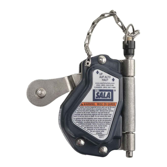
Figure 1 - Product Overview
Product
Weight
1.7 lb.
(0.77 kg)
3.0 lb.
(1.36 kg)
3.0 lb.
(1.36 kg)
Lanyard Length
2.5 ft. (0.76 m)
3.0 ft. (0.91 m)
See Table 1.
See Table 1.
A
3M
LAD-SAF
TM
Mobile Rope Grab
USER INSTRUCTIONS
5902188 Rev. D
Compatible
Lanyard Models
1246535, 1246090
1246536, 1246012
Integral only.
Integral only.
TM
© 3M 2022
Advertisement
Table of Contents

Subscribe to Our Youtube Channel
Related Manuals for 3M DBI SALA LAD-SAF 5000335


Summary of Contents for 3M DBI SALA LAD-SAF 5000335
- Page 1 1.7 lb. 5000335 (0.77 kg) 3.0 ft. (0.91 m) 1246536, 1246012 3.0 lb. 5009079 See Table 1. Integral only. (1.36 kg) 3.0 lb. 5009080 See Table 1. Integral only. (1.36 kg) © 3M 2022...
-
Page 2: Safety Information
Never exceed the maximum free fall distance specified for your Fall Protection equipment. Do not use any Fall Protection equipment that fails inspection, or if you have concerns about the use or suitability of the equipment. Contact 3M Technical Services with any questions. -
Page 3: Product Overview
Always ensure you are using the latest revision of your 3M instruction manual. Visit www.3m.com/userinstructions or contact 3M Technical Services for updated instruction manuals. PRODUCT OVERVIEW: Figure 1 illustrates available product models. Lifeline subsystems secure to a vertical lifeline to provide an adjustable anchorage connection point for the user. -
Page 4: Component Specifications
Before using this equipment, record the product identification information from the ID label in the ‘Inspection and Maintenance Log’ at the back of this manual. Table 1 – Product Specifications System Specifications: Capacity: One person with a combined weight (including clothing, tools, etc.) between 130 lb. - 310 lb. (59 kg - 140 kg). - Page 5 Table 1 – Product Specifications Integral Lanyard Specifications: Lifeline Subsystem Lanyard Specifications Model Material: 1.0 in. (25.4 mm) polyester webbing Length: 2.5 ft. (0.76 m) Connector: Model number 2100045; stainless steel swivel snap hook; gate opening 3/4-in. (19 mm); gate strength 3,600 lbf (16 kN) 5002043 Energy Absorber: Tear web;...
-
Page 6: Product Application
Hazards may include, but are not limited to: high heat, chemicals, corrosive environments, high voltage power lines, explosive or toxic gases, moving machinery, sharp edges, or overhead materials that may fall and contact the user or equipment. Contact 3M Technical Services for further clarification. - Page 7 MAKING CONNECTIONS: All connections must be compatible in size, shape, and strength. See Figure 5 for examples of inappropriate connections. Do not attach snap hooks and carabiners: To a D-ring to which another connector is attached. In a manner that would result in a load on the gate. Large-throat snap hooks should not be connected to standard- size D-Rings or other connecting elements, unless the snap hook has a gate strength of 16 kN (3,600 lbf) or greater.
-
Page 8: Installation
INSTALLATION OVERVIEW: Installing this product requires effective planning and knowledge of fall clearance requirements. In the event of a fall, there must be enough fall clearance present to safely arrest the user. PLANNING: Plan your Fall Protection system before starting your work. Account for all factors that may affect your safety before, during, and after a fall. - Page 9 See “Fall Clearance Charts” for fall clearance requirements specific to your product. Figure 6 - Fall Clearance Overview FC = FF + DD + HS + SF...
- Page 10 FALL CLEARANCE CHARTS Find your Required Fall Clearance (FC) by using the following charts. To determine Required Fall Clearance for your situation: 1. Determine your Anchorage Placement (AP). Measure the distance between your vertical lifeline’s anchorage point and your lifeline subsystem. 2.
- Page 11 CONNECTING TO ANCHORAGE: Lifeline subsystems must secure to a vertical lifeline for anchoring. See Figure 7 for reference. To connect to a vertical lifeline: Your lifeline subsystem may only be used with those vertical lifelines listed as compatible in these instructions. Lifeline subsystems must only be connected to one vertical lifeline during use.
- Page 12 BEFORE EACH USE: Verify that your work area and Fall Protection system meet all criteria defined in these instructions. Verify that a formal Rescue Plan is in place. Inspect the product per the ‘User’ inspection points defined in the “Inspection and Maintenance Log”.
-
Page 13: Maintenance, Service, And Storage
INSPECTION After equipment has been removed from service, it may not be returned to service until a Competent Person confirms in writing that it is acceptable to do so. INSPECTION FREQUENCY: The product shall be inspected before each use by a user and, additionally, by a Competent Person other than the user at intervals of no longer than one year. -
Page 14: Labels And Markings
1) Inspection Log RFID Tag LOCATION: 3M product covered in these user instructions is equipped with a Radio Frequency Identification (RFID) Tag. RFID Tags may be used in coordination with an RFID Tag Scanner for recording product inspection results. See Figure 11 for where your RFID Tag is located. - Page 15 Figure 11 - RFID Tag Location Figure 12 - Product Labels...
-
Page 16: Inspection Procedure
Table 2 – Inspection and Maintenance Log Model Number (Serial Number): Date Purchased: Date of First Use: ··· This product must be inspected by the user before each use. Additionally, a Competent Person other than the user must inspect this equipment at least once each year. ···... - Page 17 Figure 13 - Webbing Figure 14 - Energy Absorber Figure 15 - Connectors...
- Page 20 LIMITED REMEDY: Upon written notice to 3M, 3M will repair or replace any product determined by 3M to have a factory defect in workmanship or materials. 3M reserves the right to require product be returned to its facility for evaluation of warranty claims. This warranty does not cover product damage due to wear, abuse, misuse, damage in transit, failure to maintain the product or other damage beyond 3M’s control.
Need help?
Do you have a question about the DBI SALA LAD-SAF 5000335 and is the answer not in the manual?
Questions and answers