Advertisement
ETC Installation Guide
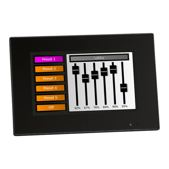
Paradigm P-TS7-E Wall-Mount Touchscreen
Overview
The Paradigm P-TS7-E Wall-Mount Touchscreen can be installed in a
flush-mount back box or a surface-mount back box (available separately).
The P-TS7-E touchscreen connects to the Paradigm control system by
Ethernet and is powered either by Ethernet with PoE 802.3af or Auxiliary
Power 24 VDC.
• Ethernet Category 5 cable (or approved equal)
• Auxiliary Power (1.5 mm
pair
Note:
should follow standard wiring installation practices. Leave approximately 25.4 cm (10 in) of
wiring in the back box for connection and to allow slack for future service needs.
For more information about terminating Cat5 cable, refer to the ETC Ethernet Cat5
Termination Kit Setup Guide.
Installation
Note:
Install the Back Box
The touchscreen is supplied with an installation kit including hardware and electrical supplies for
most installation applications. Ensure the back box is clean and free of obstructions and that all
wiring is terminated correctly prior to powering the unit.
Part Number Description
7184A1502 7" Touchscreen Flush-Mount Back Box
7184A1503 7" Touchscreen Surface-Mount Back Box
1. For flush-mount installation, mount the back box flush to the stud and carefully cut the hole in
the wall so there are no gaps around the box. For surface-mount installation, mount the
surface-mount back box to a wall surface and secure it in place. Back box mounting hardware
is not provided.
Note:
or your authorized ETC dealer for availability.
Corporate Headquarters n Middleton, WI, USA | +1 608 831 4116
Global Offices n London, UK | Rome, IT | Holzkirchen, DE | Paris, FR | Hong Kong | Dubai, UAE | Singapore
New York, NY | Orlando, FL | Los Angeles, CA | Austin, TX
Web
© 2022 Electronic Theatre Controls, Inc. | Trademark and patent info:
Product information and specifications subject to change. ETC intends this document to be provided in its entirety.
7184M2186 Rev A Released 2022-09
2
[16 AWG]) typically a black and red wire
All control wiring should be installed and terminated by a qualified installer and
Installation must follow all national and local codes for electrical equipment.
As required, a trim ring is available to cover any excess rough-in gap. Contact ETC
etcconnect.com
| Support
support.etcconnect.com
| Contact
etcconnect.com/contactETC
etcconnect.com/ip
Advertisement
Table of Contents

Related Manuals for ETC Paradigm P-TS7-E


Summary of Contents for ETC Paradigm P-TS7-E
- Page 1 | Support support.etcconnect.com | Contact etcconnect.com/contactETC © 2022 Electronic Theatre Controls, Inc. | Trademark and patent info: etcconnect.com/ip Product information and specifications subject to change. ETC intends this document to be provided in its entirety. 7184M2186 Rev A Released 2022-09...
- Page 2 ETC Installation Guide P-TS7-E Touchscreen Mounting Screw (M4) Depth Adjustment Depth Screw (M3) Adjustment Mounting Screw (M3) Mounting Pins Screw (M4) Adjustment Screw Hole Mounting Mounting Screw Hole Collar 2. The installation kit includes two lengths of screws, one length for depth adjustment of the collar in the back box, and one longer length for securing the collar to the back box.
- Page 3 ETC Installation Guide P-TS7-E Touchscreen Connect Ethernet Note: All Ethernet terminations must follow IEEE 802.3 and be terminated to the T568B standard. 1. Terminate the network wiring in the provided RJ45 punchdown block using a standard 110 punchdown tool (not provided). The connector is labeled for Cat5e wire termination color code.
- Page 4 ETC Installation Guide P-TS7-E Touchscreen Install the Touchscreen The touchscreen bracket is designed for two positions, service and operation. When installed so that the pins are in the first slots on the bracket the touchscreen is held out at the bottom for service.
Need help?
Do you have a question about the Paradigm P-TS7-E and is the answer not in the manual?
Questions and answers