PIONEER DJ DDJ-RZX Service Manual
Hide thumbs
Also See for DDJ-RZX:
- Troubleshooting manual (14 pages) ,
- Operating instructions manual (117 pages)
Table of Contents
Advertisement
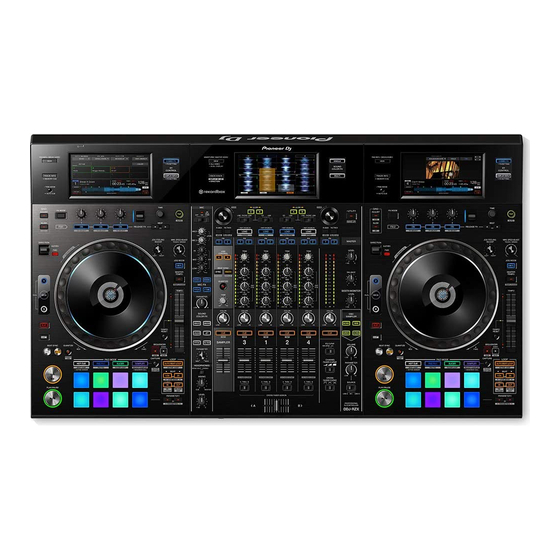
DJ Controller
DDJ-RZX
THIS MANUAL IS APPLICABLE TO THE FOLLOWING MODEL(S) AND TYPE(S).
Model
Type
DDJ-RZX
LWSYXJ
DDJ-RZX
UXJCB
DDJ-RZX
XJCN
THIS SERVICE MANUAL SHOULD BE USED TOGETHER WITH THE FOLLOWING MANUAL(S).
Model
DDJ-RZX
6F, Yokohama i-Mark Place, 4-4-5 Minatomirai, Nishi-ku, Yokohama, Kanagawa 220-0012 JAPAN
© 2016 Pioneer DJ Corporation
Power Requirement
AC 110 V to 240 V
AC 110 V to 240 V
AC 220 V
Order No.
RRV4654
SCHEMATIC DIAGRAM, PCB CONNECTION DIAGRAM, PCB PARTS LIST
DDJ-RZX
Remarks
ORDER NO.
RRV4653
Remarks
K-ZZZ JUNE
2016
Advertisement
Table of Contents

Subscribe to Our Youtube Channel
Related Manuals for PIONEER DJ DDJ-RZX


Summary of Contents for PIONEER DJ DDJ-RZX
- Page 1 THIS SERVICE MANUAL SHOULD BE USED TOGETHER WITH THE FOLLOWING MANUAL(S). Model Order No. Remarks DDJ-RZX RRV4654 SCHEMATIC DIAGRAM, PCB CONNECTION DIAGRAM, PCB PARTS LIST 6F, Yokohama i-Mark Place, 4-4-5 Minatomirai, Nishi-ku, Yokohama, Kanagawa 220-0012 JAPAN © 2016 Pioneer DJ Corporation K-ZZZ JUNE 2016...
-
Page 2: Safety Information
WARNING This product may contain a chemical known to the State of California to cause cancer, or birth defects or other reproductive harm. Health & Safety Code Section 25249.6 - Proposition 65 DDJ-RZX... -
Page 3: Table Of Contents
9.3 DISPLAY SECTION ..............................92 9.4 CONTROL PANEL SECTION (1/5)..........................94 9.5 CONTROL PANEL SECTION (2/5)..........................96 9.6 CONTROL PANEL SECTION (3/5)..........................98 9.7 CONTROL PANEL SECTION (4/5)..........................99 9.8 CONTROL PANEL SECTION (5/5)..........................101 9.9 JOG DIAL SECTION ..............................102 DDJ-RZX... -
Page 4: Service Precautions
How to replace, refer to the remarks column. Parts that is Diffcult to Replace Assy Name Ref No. Function Part No. Remarks JFLB1 Assy V6001 Repair the JOG FL and FL holder DEL1074-A JOG FL after removing them as integrated units. JFLB2 Assy V6101 DDJ-RZX... -
Page 5: Service Notice
If you need to run touch panel check, you should run factory reset before it. And select service mode, run touch panel check. The product which Firmware version is 1.05 or later is shipped after the check results have been cleared. DDJ-RZX... - Page 6 When there is no above type LED, take measures the following method. Step 1: After the power is turned off, wait 2 minutes. Step 2: Connect the Register Jig and leave the unit as it is, for 10 seconds. DDJ-RZX...
-
Page 7: Specifications
MASTER 2 output terminal RCA pin jacks ................ 1 set BOOTH output terminal 1/4” TRS jack................. 1 set PHONES output terminal 1/4" stereo jack..............1 set 3.5 mm stereo mini jack............1 set USB terminals B type ..................2 set DDJ-RZX... -
Page 8: Basic Items For Service
Part No. Remarks Lubricating oil GYA1001 Refer to "9.6 CONTROL PANEL SECTION (3/5)". Refer to "9.7 CONTROL PANEL SECTION (4/5)". Refer to "9.9 JOG DIAL SECTION". Lubricating oil GEM1034 Refer to "7 DISASSEMBLY". Refer to "9.9 JOG DIAL SECTION". DDJ-RZX... -
Page 9: Pcb Locations
JOGR1 ASSY PLAY ASSY SLDB ASSY SLDB ASSY PLAY ASSY • Bottom view PAD2 ASSY STMO ASSY HPJK ASSY CFXB ASSY PAD1 ASSY CHFD1 ASSY CHFD2 ASSY CHFD3 ASSY CHFD4 ASSY SAFD ASSY • Bottom view OSCB ASSY CRFD ASSY DDJ-RZX... - Page 10 1..UCOM ASSY DWM2602 2..CHFD3 ASSY DWX3805 2..INSL ASSY DWX3800 2..CHFD4 ASSY DWX3806 2..CFXB ASSY DWX3801 2..SAFD ASSY DWX3807 2..PSWB ASSY DWX3808 2..JOGR1 ASSY DWX3815 2..STMO ASSY DWX3824 2..JOGR2 ASSY DWX3827 1..SW POWER SUPPLY DWR1548 2..HOLD1 ASSY DWX3889 2..HOLD2 ASSY DWX3890 DDJ-RZX...
-
Page 11: Block Diagram
C K S 6 6 2 5 - A C K S 6 6 2 5 - A C K S 4 4 2 8 - A C K S 6 6 2 5 - A C K S 4 4 2 8 - A DDJ-RZX... -
Page 12: Overall Block Diagram
HP_L HP_MCLK (24.576MHz) HP_R HPMINI VR6701 MAS/BO_BCLK BCLK HPJK ASSY MIC1TRIM HP_BCLK (6.144MHz) MAS/BO_LRCLK LRCLK VR6702 HP_LRCK (96kHz) MIC2TRIM CN6701 6pin 6pin CN8001 CN8002 CN4601 JA8003 IC8003 IC8003 IC4601 MIC1 MIC1 JA8001 MIC2 MIC2 IC8002 IC8002 IC4602 MCJK ASSY DDJ-RZX... - Page 13 LCD BLOCK RESET POWER Analog Digital CN1351 LCDM ASSY LCDP ASSY CN1851 TFT Module 7inch WVGA Touch Panel TFTModule 7inchWVGA TouchPanel (Mixer, LCD3) (DECK2) CWX4352 DSX1128- CWX4352 DSX1128- CN1401 CN1381 FPC 60pin FPC 4pin FPC 60pin FPC 4pin V+9R6_LCD V+9R6_LCD RGB[6:6:6] /SHUNT V-6_LCD...
- Page 14 PANEL BLOCK RESET POWER Analog Digital DECK1 DECK2 STMO ASSY INSL ASSY CN8201 CN7007 S8202 AC AD RFX1/2 ASSY DEUP ASSY BROWSE_L0,1 BROWSE_L0,1 BROWSE_L0,1 CN7010 CN7504 KEY_L_9 KEY_L_6,7,8,9 KEY_L_6,7,8,9 CN5701 BROWSE_L CN7501 GRID_L_4 GRID_L_4,5,6,7 GRID_L_4,5,6,7 DEUP ASSY LED0,1,2,3,4 LED0,1,2_RFX LED0_RFX, LED1_RFX, LED2_RFX LED0,1,2 LED_L_0,1,2,3,4 GRID4...
-
Page 15: Power Block Diagram
MIXER SECTION DECK SECTION MAIN ASSY STMO ASSY SMPS_STBY PWR_ON JFLB1/2 ASSY VOLTAGE DETECTION V+5FL IC7001 CIRCUIT Ef voltage V+12_EUP V+12_EUP V+3R3E V+3R3E PNL1 UCOM gen. circuit IC1051 R5F364AENFA-U0 DCDC BD9328EFJ INSL ASSY FLDC+/- STBY LED V+26FL V+12A MUTE V+12A IC7005 Photo- PNL2 UCOM... -
Page 16: Matrix Table
REL_FX_2 GRID ADJUST LED_R_1 FX PARAM3 SLIP REL_FX_1 DECK 3 DECK 1 LED_R_2 START L-DOUBLE L-HALF MASTER REL_FX_3 SYNC QUANTIZE LED_R_3 TEMPO UP L-IN L-OUT FX PARAM1 PARAML LED_R_4 AUTOLOOP TEMPO DOWN T.RESET PLAY FX PARAM2 PLAY PLAY PARAMR DDJ-RZX... - Page 17 KEY_R_2 T.RESET_R LOOP_OUT_R REC_R KEY_R_3 A.LOOP_R 1/2X_R START_R SHIFT_R KEY_R_4 CAPTURE_R PAR_1_R PAR_2_R SYNC_R GRID_R_4 GRID_R_5 GRID_R_6 GRID_R_7 KEY_R_0 GRID_AD_R SAMPLER_R BEAT<_R TAP_R KEY_R_1 GRID_SLIDE_R ROLL_R BEAT>_R KEY_R_2 REV_R SLIP_REV_R KEY_R_3 SLIP_R DECK_1_R DECK_3_R LOOP_IN_R KEY_R_4 QUANTIZE_R MASTER_R 2X_R DDJ-RZX...
- Page 18 CFX_CH2 FX_VR3_R 67 pin AD_MIX1_4 BALANCE CFX_MASTER LOW_CH1 TRIM_CH1 71 pin AD_MIX1_5 MID_CH1 HI_CH1 Multiplexer TC74HC4052AF MID_CH3 HI_CH3 66 pin AD_MIX1_6 TRIM_CH3 LOW_CH3 LOW_CH4 TRIM_CH4 72 pin AD_MIX1_7 MID_CH4 HI_CH4 Multiplexer TC74HC4052AF MID_CH2 HI_CH2 65 pin AD_MIX1_8 TRIM_CH2 LOW_CH2 DDJ-RZX...
-
Page 19: Diagnosis
V+3R3D V+5R1D Highside SW 10 ms (V+5FL/V+5LED) FL POWER 77 ms V+26FL V+12LED 48.5 ms 28.5 ms V+12LED or V+26FL V+3R3FL Start with whichever comes first 661ms FLDCL+/-, V+5LED FLDCR+/- 497ms AM3352 POWER 93 ms V+3R8D V3R3D_CONT 10 ms DDJ-RZX... - Page 20 9.1 ms V+1R5DDR 24.65 ms 1 ms V+2R5VGEN3 16.4 ms V+1R8VGEN4 27.6 ms V+2R8VHIGH 1 ms 18.7 ms V+3R3VGEN6 30.7ms IMX_XPOR (PMIC output) 179.5 ms EUP UCOM EUP_IMX_XPOR 30 ms IMX6Q 32 kHz X'tal 9 ms EIM_XRST 30 ms DDJ-RZX...
- Page 21 1092 ms AUDIO CLK CLK_GEN_EN (BCLK/LRCLK) DAC_XRST 3185 ms DSP2 ADC_XRST High-Z *High-Z: Mute On, High output: Mute Off EUP_MUTE PNL1_UCOM 9.0 s MUTE cancel MUTE circuit 24.4 ms MUTE ON at startup hardware control 9.0 s (Final) 8.0 ms DDJ-RZX...
-
Page 22: Troubleshooting
IC1051 or the device connected to Is the power voltage of V+3R3E Ch 4 IC1051 is defective. (IC1051 output) 3.3 V? Confirm the connecting point of V+3R3E. The voltage is 3.3 V. Confirm the WAKE UP LED after turing ON the power SW. DDJ-RZX... - Page 23 Ch 3: TP3517 (CN3501_ pin 13) (AM_PNL1_SPI1_SCLK) Ch 4: TP3518 (CN3501_ pin 11) (AM_PNL1_SPI1_MISO) V: 2 V/div. H: 200 us/div. V: 2 V/div. H: 2 us/div. Ch 1 Ch 1 Ch 2 Ch 2 Ch 3 Ch 3 Ch 4 Ch 4 DDJ-RZX...
- Page 24 This unit is not recognized by the PC/MAC Confirm if the following items displays the connected to USB B terminal and it is unable DDJ-RZX by the Windows 7 device manager. to control. * sound, video and controller of the game...
- Page 25 V: 2 V/div. H: 10us/div. V: 2 V/div. H: 40 ns/div. Ch 1 Ch 1 Ch 1 Ch 1 Ch 2 Ch 2 Ch 2 Ch 2 Ch 3 Ch 3 Ch 4 Ch 4 Ch 4 Ch 4 DDJ-RZX...
- Page 26 Confirm the connecting path of pin 8 of IC1351 LCD Module : CWX4352 and pin 8 of 1851 (PWM signal). LCDM Assy : DWX3828 Ch 1 If there is no problem, replace the LCDM and LCDP Assy : DWX3791 LCDP Assys. Ch 2 Ch 3 Ch 4 DDJ-RZX...
- Page 27 The LEDs do not light. Is there any LED that is lit? Replacement of V+5LED High Side SW (IC1154). Identify a failure location, referring to “6.1 SERVICE MODE” . Are indications of multiple Replacement of the LED of failure points LEDs abnormal? DDJ-RZX...
- Page 28 Replacement of the FL control microcomputer. Is the FL control signal normal? If the defective microcomputer is DECK1 side, replace IC7001. And if the defective one is “ ” Ch 1 DECK3 side, replace IC7005. Ch 2 Replacement of the FL (V6001, V6101). DDJ-RZX...
- Page 29 (See “4.4 MATRIX TABLE.”) Replace the element processing microcomputer (IC7001 or IC7005). The rotary VRs, slide VRs, or pads do not function. Identify a failure location, referring to “6.1 SERVICE MODE.” Are multiple buttons/switches Replace the inoperable operating element. inoperable? DDJ-RZX...
- Page 30 Ch 1: JH6001_ pin 2 (JOGR_0) signals normal? microcomputer (IC1701) or Photointerrupter Ch 2: JH6001_ pin 1 (JOGR_1) “ ” (PC7901, PC7951) V: 1 V/div. H: 500 us/div. Ch 2 Ch 1 Replacement of the element processing microcomputer (IC1701). DDJ-RZX...
- Page 31 MAIN Assy? area of MUTE transistor and peripheral circuits. “ ” Ch 1 Replace the defective device by confirming the area where the signal is not continuous inside the JACB Assy. DDJ-RZX...
- Page 32 MUTE area of MUTE transistor and peripheral circuits. transistor of HPJK Assy? “ ” Replace the defective device by confirming the area where the signal is not continuous inside the HPJK Assy. DDJ-RZX...
- Page 33 Ch 1 Ch 1 Confirmation the USB audio Defect of the USB HUB1 and HUB2 Is the DDJ-RZX unit recognized (IC4901, IC4951) in the USB line or Can not be USB audio input and output. by the PC? MAIN CPU (IC1701).
- Page 34 OP ” ” 1-16 amplifier. MIC1 line is NG : Replace IC4601 MIC2 line is NG : Replace IC4602 Replace the ADC (IC4603) if there is no defect by confirming the ADC and peripheral circuits. DDJ-RZX...
- Page 35 1-16 Ch 1: CN4601_ pin 10 (TP4605) (MIC1) Ch 1: CN6701 (MIC1_IN) Ch 1: C4611 V: 1 V/div. H: 500 us/div. V: 50 mV/div. H: 500 us/div. V: 1 V/div. H: 500 us/div. Ch 1 Ch 1 Ch 1 DDJ-RZX...
- Page 36 V+3R3A V+1R5_AM_DDR MAIN Assy TP1606 1.46V 1.50V 1.55V 1.512V ±3% V+1R8_AM_VDD MAIN Assy TP1607 1.75V 1.80V 1.85V 1.802V ±3% VDIG2 MAIN Assy TP1601 1.75V 1.80V 1.85V 1.820V ±3% V+1R8_AM_PLL VAUX33 MAIN Assy TP1602 3.20V 3.30V 3.40V 3.310V ±3% V+3R3_AM_USB DDJ-RZX...
- Page 37 LCDM Assy TP412 1.46V 1.50V 1.55V 1.502V ±3% LCDM Assy, LCDP Assy TP417 3.10V 3.30V 3.50V 3.258V ±6% V+3R3D 42-A - 42-E LCDM Assy, LCDP Assy TP1502 3.30V 3.255V JFLB1 Assy TP6023 3.538V V+3R3FL 3.3V JFLB2 Assy TP6123 3.556V DDJ-RZX...
-
Page 38: Monitoring Of Power Supply And Voltage
-5.33 V -4.11 V -3.13 V V+12D 7.33 V 8.74 V 10.50 V 16.52 V 19.50 V 23.16 V V+15A 11.95 V 12.56 V 14.64 V -9.68 V -7.71 V -6.11 V V-15A -20.61 V -19.07 V -17.58 V DDJ-RZX... -
Page 39: Operation Check With Rekordbox
• Be sure to use rekordbox Version 4.2.0 or later, because the prior versions of rekordbox do not support the DDJ-RZX. • To use rekordbox dj, rekordbox dvs, and rekordbox video, activation (license authentication) is required. For details, see the rekordbox Operating Instructions. - Page 40 2 Turn the rotary selector and select the track. 3 Press the [DECK1] button. 4 Press the [LOAD] button to load the selected track onto the deck. DDJ-RZX...
- Page 41 5 Turn the [MASTER LEVEL] (1) control to adjust the audio level of the speakers. Monitoring sound with headphones Set the positions of the controls, etc., as shown below. 1 Press the headphones [CUE] (9) button for the channel 1. 2 Turn the [HEADPHONES LEVEL] (8) control. DDJ-RZX...
-
Page 42: Service Mode
Normal end or press either Press the either BACK button hold the BACK buttons on BACK button on the right and BACK button on the right and on the right and left DECK. the left and right decks. left DECK. left DECK. DDJ-RZX... - Page 43 (Each result of the left LCD, center LCD and right LCD is displayed in order from left to right.) 1-2 2-a: Version indication mode The each microcomputer version indication and destination (language) is displayed on the center LCD. Version Information System 1.00 1.00 1.00 Main 1.00 1.00 1.00 SRC-DSP 1.00 Language English DDJ-RZX...
- Page 44 SOUND COLOR FX PARAMETER control MASTER LEVEL control, MASTER OUT COLOR control, Turn Master level indicator (right) (*4) BOOTH MONITOR control, OSC SAMPLER PARAMETER control, OSCILLATOR VOLUME control, BALANCEcontrol Cross fader Slide Performance pads, PAD mode (*5) Press Own LED DDJ-RZX...
- Page 45 Each operating element on decks 1 to 4 is represented by the corresponding channel level indicator; for a CH1 operating element, the CH1 channel level indicator is used, for a CH2 operating element, the CH2 channel level indicator is used, and so on. DDJ-RZX...
- Page 46 CH3 Channel fader CH1 TRIM CH1 EQ/ISO High CH1 EQ/ISO Mid CH1 EQ/ISO Low CH1 COLOR CH1 Channel fader CH2 TRIM CH2 EQ/ISO High CH2 EQ/ISO Mid CH2 EQ/ISO Low CH2 COLOR CH2 Channel fader CH4 TRIM CH4 EQ/ISO High DDJ-RZX...
- Page 47 [ Operating elements for Test object] At the following figure, the number enclosed in blue displays the operating elements for Test object, and the number enclosed in black displays the indicator for showing operating elements for Test object. Refer to the latter figure DDJ-RZX...
- Page 48 5 To reset the fluctuation values up until the present, press the rotary selector while monitoring A/D conversion values. To reset the monitored A/D values, press the rotary selector. All LEDs will go dark. The A/D conversion value when the rotary selector is pressed will become a new reference value. DDJ-RZX...
- Page 49 When the SYNC buttons on the left and right decks are simultaneously held pressed, the LEDs of these buttons light. After resetting is completed, the pads on both decks light in blue. When resetting has failed, the SYNC buttons on both decks flash. BPM DOWN BPM UP Simultaneously hold both SYNC buttons pressed for 1 sec. DDJ-RZX...
- Page 50 3 Slide the crossfader to its rightmost position then press pad 5 on the right deck. The color of pad 5 changes to green. (The minimum value for the crossfader is obtained.) BPM DOWN BPM UP Slide the crossfader to its rightmost position then press pad 5 on the right deck. DDJ-RZX...
- Page 51 If no calibration was performed, no level indicators light. The pressed PAD (left PAD 8/ right PAD 5) lit in white. [Error indication when no calibration is performed] With no calibration, the Jog ring LEDs on the left deck flash in blue. BPM DOWN BPM UP DDJ-RZX...
- Page 52 The FX1, FX2, FX3, and TAP buttons on the left and right decks light. The PLAY/PAUSE button on the left deck lights. The FX assign buttons on the mixer lights. SOUND COLOR FX SELECT button (SPACE, CRUSH, DUB ECHO, JET), OSC SAMPLER SELECT button light. DDJ-RZX...
- Page 53 Note: To weigh a pad down, be sure to place a weight (12 mm dia.) on the center of the pad, with the convex part (contact area dia.: 10 mm) facing downward. Weight for pad calibration Be sure to place a weight on the center of the pad. Performance pad DDJ-RZX...
- Page 54 *If the CH3 Headphones CUE and CH4 Headphones CUE buttons are pressed without setting the A/D conversion value, an error indication will be displayed. (All of PAD is flashing red) DDJ-RZX...
- Page 55 Simultaneous pressing of the FX MODE and TAG TRACK (RELATED LIST) buttons on the left and right decks deletes the setting values stored in the serial flash memory. BPM DOWN BPM UP Deletion is completed when the color of all pads changes to white. DDJ-RZX...
- Page 56 : Pads 1 to 4 on the right deck SAMPLER mode button : Pads 5 to 8 on the right deck 3 The level indicator oscillates in response to force applied to the pad. [HOTCUE] BPM DOWN BPM UP DDJ-RZX...
- Page 57 [PAD FX1] BPM DOWN BPM UP [SLICER] BPM DOWN BPM UP [SAMPLER] BPM DOWN BPM UP DDJ-RZX...
- Page 58 • The number of sessions (1–4) in which the time required for slowdown was 100 msec or shorter is indicated with the SLIDE, SLIP, SYNC, and MASTER buttons on the same deck as the Jog dial being tested is located. Any such sessions exceeding five will not be counted. DDJ-RZX...
- Page 59 1 Simultaneously press the FX3 buttons on the left and right decks in Service mode (1-1: Adjustment information mode) The FX3 button on the left and right decks lights. Pad 5 and pad 1 on the left and right decks light in red. DDJ-RZX...
- Page 60 The color of pad 1 on the left deck changes to green. (The minimum value for the RELEASE FX lever is obtained.) If the obtained value is incorrect, an error indication will be displayed. BPM DOWN BPM UP Execute the right DECK same way. Replace the "left DECK" to "right DECK". (Repeat 2 to 3.) DDJ-RZX...
- Page 61 The hundreds, tens, and unit's digits are expressed with the CH1, CH2, and CH4 level indicators, respectively. If no calibration was performed, no level indicators light. [Error indication when no calibration is performed] When the calibration is not executed, the RELEASE FX indicator on the no calibration side is flashing. BPM DOWN BPM UP DDJ-RZX...
- Page 62 And when the BACK button is pressed on the way, the calibration value is not stored and the touch panel calibration mode is finished, (Returns to service mode (1-1: Adjustment information mode), and displays the result). And the lower right side square button of LCD blinks for caution in this case. DDJ-RZX...
- Page 63 When there is a difference between each pictures, adjust again by right side button of each LCD. 5 Exit from the mode by pressing either right and left DECK BACK button. *When adjusting brightness by the UTILITY mode, the offset part in primary adjustment is reflected. DDJ-RZX...
-
Page 64: About The Device
BD2232G-G-TRB IC1154, IC1155, MAIN Assy IC1157, IC1452, IC1453, IC1454 PNL UOCM Standby control R5F364AENFA-U0 IC7001, IC7005 STMO Assy (PNL1/PNL2) Transferring the operation buttons data to AM3352 JOG FL For displaying JOG information DEL1074-A V6001, V6101 JFLB1 Assy, JFLB2 Assy DDJ-RZX... -
Page 65: Disassembly
DAA1307 DAA1300 DAA1305 DAA1368 DAA1309 Black Black Silver Gray Black Gray White White White White White White White DAA1250 DAC2685 DAC2684 DNK5888 DAC2685 DAC3238 DNK6440 Black DAC2685 DAC2685 White White White DAC2684 DAC3238 Black Black Gray DNK5888 DNK6440 Gray DDJ-RZX... - Page 66 (3) Remove the 24 screws. (BBZ30P100FTB) • Bottom view (4) Remove the Control panel section. (5) Disconnect the 2 flexible cables and Bottom section 1 connector. (CN3501, 3551, 4501) Jumper wires styling CN4501 CN3501 CN3551 MAIN Assy Control panel section HOLD2 Assy DDJ-RZX...
- Page 67 • Rear view MTRM Assy (3) Remove the 2 screws. (DBA1260) (4) Disconnect the MTRM Assy with stay from the connector. (CN8001) (5) Remove the Chassis with PC boards, by removing the 9 screws. CN8001 (BPZ30P080FNI) Cord clamper Chassis DDJ-RZX...
- Page 68 (5) Disconnect the 2 flexible cables and 2 connectors. MCJK Assy MAIN Assy JACB Assy (CN1001, 3451, 3701, 4601) (6) Remove the MAIN, JACB and MCJK Assemblies, by removing the 14 screws. (BBZ30P060FTC) CN4601 CN3701 Cord Cord clamper clamper CN3451 CN1001 DDJ-RZX...
- Page 69 Left display • Bottom view (3) Remove the Angle, by removing the 2 screws. Let, right display Center display (BBZ30P080FTB) (4) Remove the 2 Angles, by removing the Angle Angle 2 screws. (BBZ30P080FTB) Angle Angle Angle Angle • Bottom view DDJ-RZX...
- Page 70 (8) Remove the Bracket, by removing the 4 screws. (BPZ30P080FNI) (9) Remove the TFT LCD. Bracket (10) Remove the Touch panel. (11) Remove the Plate/GND. TFT LCD Touch panel Plate/GND Jumper wires styling TFT LCD Slit TFT LCD Slit DDJ-RZX...
- Page 71 *: During reassembly, fully push down Slider knob 2 until it is dented into Slider knob 1. 4 Remove the Slider knob 1 (knob). 5 Remove the Slider knob stopper (Stopper). Slider knob 1 (knob) Slider knob stopper (Stoper) DDJ-RZX...
- Page 72 (2) Remove the 2 Cord clampers, by removing the 2 screws. (BPZ30P080FNI) (3) Disconnect the 6 flexible cables. (CN7010-7015) (4) Remove the 2 Sheets, by removing the 8 screws. (BPZ30P080FNI) Sheet Sheet Cord clamper • Bottom view Jumper wires styling Sheet Cord clamper Cord clamper Sheet DDJ-RZX...
- Page 73 (3) Remove the Torsion Spring/LVR. (4) Remove the RFX1 (RFX2) Assy, by removing Torsion Spring/LVR the 2 screws. (BPZ30P080FNI) (5) Remove the Lever. RFX1 (RFX2) Assy Torsion Spring/PRS Refer to "6.1 SERVICE MODE 1-8: RELEASE FX lever adjustment mode". Lever DDJ-RZX...
- Page 74 Note: Be sure to insert the hook section of the lever into the VR lever. [4] Jog dial Section (1) Remove the Jog dial section, by removing the 12 screws. (BPZ30P080FNI) Screw tightening order Jog dial Section Jog dial Section • Bottom view DDJ-RZX...
- Page 75 1-7: Measurement mode of the load of JOG dial”. • Bottom view (2) Unhook the 3 hooks. Jog Section (3) Remove the Jog Section. (4) Remove the 3 screws. (DBA1265) SW ring (5) Remove the SW ring. Note: Be careful not to lost SW spring. SW spring DDJ-RZX...
- Page 76 5. When making a connection, be sure to first release the lock of the connector then securely Holder relock the connector after making the connection. Holder Pasting position of the SW cushion HH48/2 SW cushion HH48/2 ( 9) Sheet SW DDJ-RZX...
- Page 77 Link gear A Reference information Screw tightening order (JFLB1 / JFLB2 Assy) Screw tightening order (Link plate) The other screws are random order. The other screws are random order. JFLB1 / JFLB2 Assy Link plate • Bottom view • Bottom view DDJ-RZX...
- Page 78 Crossfader Section Holder (4) Remove the Slider section, by removing the Stay 1 screw. (CPZ26P080FTC) (5) Remove the Stay, by removing the 3 screws. (BBZ30P060FTC) (6) Remove the CRFD Assy, by removing the 2 screws. (BPZ20P050FTC) CRFD Assy Slider Section DDJ-RZX...
- Page 79 • Mixer Section (1) Remove the 3 Cord clampers, by removing Cord clamper Sheet the 3 screws. (BPZ30P080FNI) (2) Remove the Sheet, by removing the 6 screws. (BPZ30P080FNI) Jumper wires styling Insert Sheet Cord clamper DDJ-RZX...
- Page 80 (BPZ30P080FNI) • Bottom view (4) Remove the 4 screws. (BBZ30P060FTC) (5) Remove the 36 screws. (BPZ30P080FNI) • Bottom view (6) Remove the 11 screws. (BPZ30P080FNI) (7) Remove the 10 screws. (BPZ30P100FTC) (8) Remove the Mixer section. • Bottom view DDJ-RZX...
- Page 81 CFXB Assy MIXA Assy OSCB Assy Slide SW Cap (W) • Channel fader Section (1) Remove the 5 Channel fader sections, by Channel fader Section removing the 10 screws. (BSZ20P040FTB) Screw tightening order The other screws are random order. DDJ-RZX...
- Page 82 Top & Bottom Top & Bottom After applying grease, move the slider base back and forth from one end to the other for approximately 10 to 20 strokes, in order to fully spread the grease. Shaft holder Top & Bottom Top & Bottom DDJ-RZX...
-
Page 83: Each Setting And Adjustment
• RELEASE FX lever adjustment (calibration) (RFX1 (RFX2) Assy, Lever, Torsion Spring/LVR, Torsion Spring/PRS, Holder) • Jog dial section component part • Confirmation of the specified value by Jog dial Rotation (See "9.7 JOG DIAL SECTION".) Time measurement mode DDJ-RZX... -
Page 84: Updating Of The Firmware
For MacOS: The [DDJ-RZX_vxxx_MAC_E] folder is generated when the file is extraced. · If the message “Your DDJ-RZX is not connected” is Please ensure the following file is included in the folder. displayed when you click on [OK], see “Corrective actions [DDJ-RZX_vxxx.app]... - Page 85 If updating failed: If the error message shown below is displayed during It will take approximately 3 minutes to complete the updating, turn off the DDJ-RZX then proceed with the steps update process. from the beginning. The screen displays shown in this manual are under development and are subject to change.
-
Page 86: Items For Which User Settings Are Available
Limiter ON (enabled) / Limiter OFF (Disabled) audio added to booth output Each of the above items can be set in Utilities screen. Press the [WAKE UP (UTILITY)] button for over 1 second. The utilities screen appears on a center display of this unit. DDJ-RZX... - Page 87 Monaural/stereo setting of booth output MONO STEREO MONO STEREO Operation setting of microphone sound low cut filter enabled disabled Limiter setting of microphone audio added to master output Limiter setting of microphone audio added to booth output enabled disabled enabled disabled DDJ-RZX...
-
Page 88: Exploded Views And Parts List
9. EXPLODED VIEWS AND PARTS LIST 9.1 PACKING SECTION LWSYXJ, LWSYXJ UXJCB only only XJCN LWSYXJ, LWSYXJ, LWSYXJ, only UXJCB UXJCB UXJCB only only only Front Front DDJ-RZX... - Page 89 See Contrast table (2) 22 Carton See Contrast table (2) NSP 23 Other Card See Contrast table (2) (2) CONTRAST TABLE DDJ-RZX/LWSYXJ, UXJCB and XJCN are constructed the same except for the following: DDJ-RZX DDJ-RZX DDJ-RZX Mark Symbol and Description...
-
Page 90: Chassis Section
9.2 CHASSIS SECTION Accessories of the VR Refer to "9.4 CONTROL PANEL SECTION (1/5)". Refer to Tape "9.3 DISPLAY SECTION". DDJ-RZX... - Page 91 DNF1984 49 Screw PPZ30P080FTB 24 Cover DNH3254 50 Screw BBZ30P100FTB 25 Bracket DNH3255 (2) CONTRAST TABLE DDJ-RZX/LWSYXJ, UXJCB and XJCN are constructed the same except for the following: DDJ-RZX DDJ-RZX DDJ-RZX Mark Symbol and Description /LWSYXJ /UXJCB /XJCN Plate DAK1006...
-
Page 92: Display Section
9.3 DISPLAY SECTION Center Left and Right for L for R AG AH MAIN CN4901 MAIN CN3401 • Bottom view DDJ-RZX... - Page 93 26 Sheet DEC3678 27 Bracket DNF1991 28 Plate/GND DNH3173 29 Angle DNH3256 30 Angle DNH3277 31 Angle DNH3278 32 Holder DNK6612 33 • • • • • 34 • • • • • 35 Screw BBZ30P080FTB 36 Screw BPZ30P080FNI DDJ-RZX...
-
Page 94: Control Panel Section (1/5)
CN8201 OSCB DEUP CN8401 CN7504 JFLB2 CN6102 MIXA CN9001 MIXA PAD2 CN9002 CFXB CN5301 CN8301 MAIN CN3551 MAIN CN3051 DEUP CN7504 JFLB1 CN6002 PAD1 CN5001 Refer to "7. DISASSEMBLY" Tape MAIN CN4501 Refer to "9.5 CONTROL PANEL SECTION (2/5)". DDJ-RZX... - Page 95 36 DS Tape DEH1086 37 Knob/SLD DNK5981 NSP 38 Cushion DEC3356 39 Stay DNF1942 40 Lever DNH3211 41 Holder DNK6425 42 Slider DNK6426 43 Guide Bar VLL1514 44 • • • • • DEA1056 45 • • • • • DEA1057 DDJ-RZX...
-
Page 96: Control Panel Section (2/5)
CN7005 STMO CN7004 STMO CN7007 Accessories Accessories of the VR of the VR Refer to "9.6 CONTROL PANEL SECTON (3/5)". Refer to "9.9 JOG DIAL SECTION". Refer to "9.9 JOG DIAL SECTION". Refer to "9.7 CONTROL PANEL SECTON (4/5)". DDJ-RZX... - Page 97 DEC3667 20 Sheet DEC3683 21 Sheet DEC3684 22 Stay DND1306 23 Stay DNF2004 24 Cord Clamper (Steel) RNH-184 25 • • • • • 26 • • • • • 27 Screw BBZ30P060FTC 28 Screw BPZ30P080FNI 29 Screw BPZ30P100FTC DDJ-RZX...
-
Page 98: Control Panel Section (3/5)
25 • • • • • 10 FFC DDD1743 26 Screw BSZ20P040FTB 11 FFC DDD1744 27 Screw BPZ20P060FTC 12 FFC DDD1789 28 Screw CPZ26P080FTC 13 Connector Assy PF03PP-C12 29 Screw PMH20P040FTC 14 Connector Assy PF03PP4B12 15 Level Meter Assy DXB1882 DDJ-RZX... -
Page 99: Control Panel Section (4/5)
Amount of grease to be applied to the lever Screw tightening order • Top view Base Too little Normal Too much DEUP CN7501 1/2, 1/2, 2/2 1/2, DEUP CN7501 1/2, 2/2 1/2, 2/2 1/2, Refer to "9.8 CONTROL PANEL SECTION (5/5)". DDJ-RZX... - Page 100 34 Button DAC3228 35 Button DAC3226 36 Button DAC3227 37 Button DXB2174 38 Ring Rens (PLAY) DNK5315 39 Lens/TMP DNK6307 40 Lever DAC2804 41 Torsion Spring/LVR DBH1790 42 Torsion Spring/PRS DBH1791 43 Cushion DEB1999 44 Holder/LVR DNK6025 45 Lens DNK6620 DDJ-RZX...
-
Page 101: Control Panel Section (5/5)
Mark No. Description Part No. Mark No. Description Part No. 6 Panel DNK6614 1 Frame DNH3260 7 Panel DNK6615 2 Frame DNH3261 8 Screw BBZ30P060FTC 3 Frame DNH3262 9 Screw BPZ30P100FTC 4 Frame DNH3263 10 Screw PMB30P060FTC 5 Frame DNK6613 DDJ-RZX... -
Page 102: Jog Dial Section
9.9 JOG DIAL SECTION Holder Lubricating oil (GYA1001) Lubricating oil (GEM1034) Lubricating oil (GEM1034) Lubricating oil Lubricating oil (GEM1034) (GEM1034) Lubricating oil STMO (GYA1001) CN7011 (L) CN7013 (R) Lubricating oil (GYA1001) DDJ-RZX... - Page 103 27 Stay Assy/Jog DXB2133 28 Encoder Spring DBH1710 29 Plate DEC3700 30 Gear/A DNK6143 31 Gear/B DNK6144 32 Leaf Spring/ADJ DBK1376 33 Jog Panel DAH2609 34 FFC DDD1746 35 Screw (FE) DBA1265 36 Screw BPZ20P100FTC 37 Screw BPZ30P080FNI 38 Screw IPZ20P060FTC DDJ-RZX...
Need help?
Do you have a question about the DDJ-RZX and is the answer not in the manual?
Questions and answers