Table of Contents
Advertisement
Quick Links
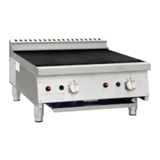
Gas Char Grill
Installation and Operation Instructions
Model: DC331-N, DC331-P, CF380-N, CF380-P
IMPORTANT FOR FUTURE REFERENCE
Please complete this information and retain this manual for the life of the equipment. For
Warranty Service and/or parts, this information is required.
Model Number
WARNING: For your safety, do not store or use gasoline or other flammable vapors or
liquids in the vicinity of this or any other appliances. Keep the area free and clear of
combustible materials.
WARNING:Improper installation, adjustment, alteration, service or maintenance can
cause property damage, injury, or death. Read the installation operating and
maintenance instructions thoroughly before installing, or servicing this equipment.
WARNING:Instructions must be posted in a prominent location. All safety precautions
must be taken in the event the user smells gas. Safety information can be obtained from
your local gas supplier.
WARNING:Components must not be cleaned in a dishwasher
Serial Number
Nisbets PLC
Fourth Way, Avonmouth, Bristol, BS11 8TB,
Unit 9003, Blarney Business Park, Blarney,Co. Cork
Date Purchased
Advertisement
Table of Contents

Related Manuals for Buffalo DC331-N


Summary of Contents for Buffalo DC331-N
- Page 1 Gas Char Grill Installation and Operation Instructions Model: DC331-N, DC331-P, CF380-N, CF380-P IMPORTANT FOR FUTURE REFERENCE Please complete this information and retain this manual for the life of the equipment. For Warranty Service and/or parts, this information is required. Model Number...
-
Page 2: Table Of Contents
Table of Contents Introduction ................3 ..Specifications ................4 Installation Guide ................ 6 III. Operation Guide ................ 13 Cleaning Instructions ..............17 Gas Conversion ................. 19 VII. Troubleshooting Guide ..............23 VIII.Exploded View ................30 Spare Parts List ................. 32... -
Page 3: Introduction
Introduction CE Only: These instructions are only valid if the country code appears on the appliance. If the code does not appear on the appliance, refer to the supplier of this appliance to obtain the technical instructions for adapting the appliance to the conditions for use in that country. VERY IMPORTANT! READ THIS FIRST Before installing and operating this equipment, ensure that everyone involved in its operation are fully... -
Page 4: Specifications
Specifications General A commercial heavy-duty gas Char-Grill. It uses lava rocks or cast radiants. Pack Contents Buffalo Gas Char-Grill Cast Radiant (Standard), Lava Rocks (Optional) Gas Stand Instruction Manual Dimensions Depth Models Length (mm) Height (mm) (mm) DC331-P DC331-N CF380-P... - Page 5 Gas Specification Table Natural Gas Propane Butane Gas Type (G20) (G31) (G30) DC331-P DC331-N DC331-P Models CF380-N CF380-P CF380-P Single burner Heat 7.15 7.15 7.15 Input (KW) No. of burners Total Heat Input (KW) 14.3 14.3 14.3 Manifold Pressure (mbar)
-
Page 6: Installation Guide
Installation Guide III. Installation Requirements Only qualified and/or authorized persons must carry out the installation, gas conversion, and servicing/repair of this equipment. Components having adjustments protected by the manufacturer are not to be adjusted by the installation person. They must only be adjusted by an authorized Service Engineer. This equipment must be installed in an area with sufficient ventilation to prevent the occurrence of unacceptable concentrations of substances harmful to health. - Page 7 Do not put the equipment in an area where the equipment’s flue may be obstructed. Also, do not directly connect the equipment’s flue to any ventilation equipment or system. Any gas burning appliance requires adequate clearance and ventilation for optimum and trouble- free operation.
- Page 8 Install the Flue Remove the Flue from the packaging, then remove all protective film from the flue. Install the flue at the back of the unit by pushing it down. Flue Install the cast radiants (for units with cast radiants) Remove the cast radiants from the packaging.
- Page 9 Install the Lava Rock Kit (for units with Lava Rock Kit) Remove the lava rocks and support racks from the packaging. Then, position the support racks over the burner tubes. The support racks should rest firmly on the front and back support flange. See image below. Support Rack Place the lava rocks over the support rack as shown in the photo below.
- Page 10 Install the top cast grates/grills Remove the top cast grates from the packaging. Install the top cast grates. Horizontal installation: Place each cooking grate on the front support flange horizontally while the rear part sits into the back support flange horizontally. See image below. Cast Grates Grease trough (Horizontal)
- Page 11 Gas Connection Only qualified and/or authorized persons must carry out the gas connection, testing and commissioning of this equipment. After installing all the necessary parts, position the equipment in its final operating position. Before connecting the gas supply line to the equipment, check the following: Check gas type that will be supplied to the equipment.
- Page 12 Remove the plug from the Manifold Pressure Test Point and install a portable manometer. Check for gas leak on the connection. Turn ON the isolation gas valve, and open one burner and set at “High Flame” for Check the pressure reading in the manometer. The manometer pressure reading should be according to the pressure of the gas type indicated in the rating label and on the Gas Specification Table on page 5 of this manual.
-
Page 13: Operation Guide
Operation Guide This equipment is only for professional use and that it shall be used by qualified persons. Parts or components that have adjustments which are protected by the manufacturer or his agents shall not be adjusted by the user/ operator. Equipment Controls OFF Position Flame Viewing Hole... - Page 14 Lighting the Pilot Burners The burners of this Gas Char-Grill are fitted with individual standing pilots which allows the main burners to be turned ON or OFF without the need to manually re-light the burner each time that it is turned OFF, as the burner will automatically light itself by the pilot burner. Flame Failure Protection is incorporated for each burner by way of a thermo-electric system which will shut off the gas supply to that burner in the event that the pilot burner flame goes out, so that un-burnt gas is not expelled to the surrounding area.
- Page 15 Main burner air supply: For efficient burner operation, a proper balance of gas volume and primary air supply must be maintained which will result in complete combustion. Insufficient air supply results in a yellow streaming flame. The primary air supply is controlled by an air shutter on the front of the burner. Loosen the lock screw on the front of the burner and adjust the air shutter to just eliminate the yellow tips of the burner flame.
- Page 16 Start-up operation or operation from cold start Turn the burners on about 5 minutes before cooking for preheating. Set the knobs to the desired temperature setting or temperature. Each valve will control the gas flow to the burner to bring that area of the unit up to the set temperature. If different temperature settings are to be used, adjoining areas should be set at progressively higher temperatures using the lowest temperatures on the outside burners.
-
Page 17: Cleaning Instructions
Cleaning Instructions CAUTION! Always turn the unit OFF, and follow the lock-out/tag-out procedure before performing cleaning and maintenance operation. Allow the unit to cool down first, before starting any cleaning and maintenance operation. INITIAL CLEANING: Prior to operating your new Char-Grill, perform the Cast Grates “Burn-OFF”, when the Char- Grill is first heated, it will smoke until oil used in manufacturing, preservation and dust from storage and shipping are burned off. - Page 18 WEEKLY CLEANING: Remove the grease pan, empty and wash it with mild detergent and warm water, applied by sponge or soft cloth. Then, dry it with a soft dry cloth. To remove normal dirt, clean the flue and exterior body of the equipment with mild detergent and warm water, applied by sponge or soft cloth.
-
Page 19: Gas Conversion
Gas Conversion CAUTION! Only qualified/authorized service persons are to carry out gas conversion operations. Before proceeding with the gas conversion procedure, allow the unit to cool down first, and ensure that the main gas supply connected to the equipment is shut-off, and lock-out/tag- out procedure is followed, to prevent injury to persons or damage to properly. - Page 20 Replace the Pilot Injectors Remove the pilot cover. Slacken the two screws of the pilot cover and remove it. Allen screws Pilot Cover Disconnect the pilot pipe assembly from the pilot injector. Slacken the nut of the pilot pipe to allow for easy removal. Use 10mm spanner Pilot pipe Pilot Injector/ assembly...
- Page 21 Adjust the inlet pressure according to the gas type used. Refer to the equipment’s rating label or the Gas Specification Table on page 5 of this manual. Turn ON the isolation gas valve, and open one burner and set at “High Flame” Check the pressure reading in the manometer.
- Page 22 Gas Conversion Kits DC331-N/DC331-P Item Name Char-Grill Model No. CF380-N/CF380-P Single Supply Manifold Pilot Country of Main Burner burner Category Pressure Pressure Burner destination Injectors Heating (mbar) (mbar) Injectors Input(KW) AT, BG, CZ, DK, EE, FI, GR, HR, HU, IS, IE, IT, 0.45...
-
Page 23: Vii. Troubleshooting Guide
VII. Troubleshooting Guide GENERAL INFORMATION ON TROUBLESHOOTING: Burning speed: The velocity at which flame travels through an air-gas mixture. Burning speeds vary with types of gases, and the amount of air mixed with the gas. This air to gas ratio is very important in that it is directly related to flame stability. - Page 24 Burner problems LIFTING FLAMES: How to recognize: When lifting flames occur, part of the flame lifts from the burner port. Lifting flames rise from the ports to burn some distance above the port. In some cases, these flames will drop back to the port and lift again intermittently.
- Page 25 How to correct: Yellow tipping is caused by a lack of enough primary air. This condition may be due simply to an incorrect air shutter adjustment. If this is the case, open air shutters to get rid of the yellow tips.
- Page 26 established. When the appliance heats up it should operate in a normal manner. GAS ODOR AT PRIMARY AIR OPENINGS: Under normal burner operation, a negative pressure (vacuum) should exist inside the primary air openings of a burner, drawing in air. If all gas fed to the burner by the orifice does not flow to the burner head, some gas may spill from the primary air openings.
- Page 27 Technical Troubleshooting Guide Fault Possible Cause Remedy No gas supply or gas Ensure gas isolation valve is turned on, and isolation valve is OFF. that gas tanks are not empty. Pilot burner is Check the pilot burner if clogged, and clean, or clogged/blocked.
- Page 28 Fault Possible Cause Remedy Check the gas type used, change to the correct Wrong gas type used. gas type. Check the orifice installed. Replace it with Burner and Pilot flame Wrong orifice installed. correct orifice for the gas type used. color is yellow.
- Page 29 Fault Possible Cause Remedy Adjust the air shutter to eliminate lifting of Too much primary air. flames. Lifting of flames or Blowing Flames Wrong size of injector orifice Check the orifice size of the injector installed. installed. Replace injector if necessary. Adjust the air shutter of the burner to minimize Too much primary air.
-
Page 30: Viii.exploded View
VIII. Exploded View Model: DC331-N, DC331-P... - Page 31 Model: CF380-N, CF380-P...
-
Page 32: Spare Parts List
Spare Parts List Model: DC331-N, DC331-P SUPPLIER CODE DESCRIPTION QTY. 06.15.1473545 Flue Assembly. 01.05.1031811 Cast grate hanger 06.05.1473542 CB weld Assembly 01.03.1015028 Cast iron grill 01.03.1015048 Cast Radiant 06.05.1470384 U Burner 06.05.1473546 Frame weld assy 01.22.1069541 Flame Device System (LPG)... - Page 33 Spare Parts List Model: CF380-N, CF380-P SUPPLIER CODE DESCRIPTION QTY. 06.15.1473545 Flue Assembly. 01.05.1031811 Cast grate hanger 06.05.1473542 CB weld Assembly 01.03.1015028 Cast iron grill 06.05.1472464 Lava Rock Kit 01.03.1015106 Racks 06.05.1470384 U Burner 06.05.1473546 Frame weld assy 01.22.1069541 Flame Device System (LPG)...
- Page 36 DC331-P_DC331-N_ML_A4_V1_Rev 0_20220310...
Need help?
Do you have a question about the DC331-N and is the answer not in the manual?
Questions and answers