Table of Contents
Advertisement
Quick Links
SERVICE MANUAL
P a d s
P a d s
P a d s
P a d s
K n o b s
K n o b s
K n o b s
K n o b s
B u t t o n s
B u t t o n s
B u t t o n s
B u t t o n s
C o n n e c t i o n s
C o n n e c t i o n s
C o n n e c t i o n s
C o n n e c t i o n s
P o w e r
P o w e r
P o w e r
P o w e r
D i m e n s i o n s
D i m e n s i o n s
D i m e n s i o n s
D i m e n s i o n s
( w i d t h x d e p t h x h e i g h t )
W e i g h t
W e i g h t
W e i g h t
W e i g h t
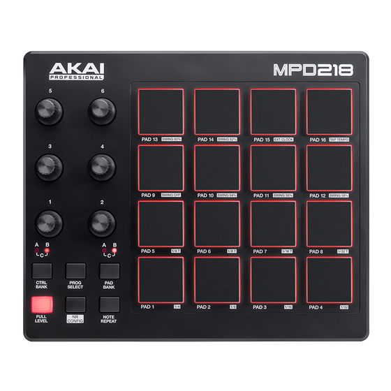
SPECIFICATIONS
1 6 1 6 1 6 1 6
v e l o c i t y - a n d p r e s s u r e - s e n s i t i v e p a d s , r e d - b a c k l i t
3 3 3 3
b a n k s a c c e s s i b l e v i a
6 6 6 6
3 6 0 ° a s s i g n a b l e p o t e n t i o m e t e r s
3 3 3 3
b a n k s a c c e s s i b l e v i a
6 6 6 6
b u t t o n s
1 1 1 1
U S B p o r t
1 1 1 1
K e n s i n g t o n l o c k
v i a U S B c o n n e c t i o n
9 . 4 " x 7 . 9 " x 1 . 6 "
2 3 . 9 c m x 2 0 . 1 c m x 4 . 1 c m
1 . 6 5 l b s .
0 . 7 5 k g
MODEL: MPD218
P a d B a n k
P a d B a n k
P a d B a n k
P a d B a n k
b u t t o n
C o n t r o l B a n k
C o n t r o l B a n k
C o n t r o l B a n k
C o n t r o l B a n k
b u t t o n
Advertisement
Table of Contents

Related Manuals for Akai MPD218


Summary of Contents for Akai MPD218
- Page 1 SERVICE MANUAL MODEL: MPD218 SPECIFICATIONS 1 6 1 6 1 6 1 6 v e l o c i t y - a n d p r e s s u r e - s e n s i t i v e p a d s , r e d - b a c k l i t...
-
Page 2: Disassembly Procedures
DISASSEMBLY PROCEDURES DISASSEMBLE THE BOTTOM PANEL AND KNOB. (A) REMOVE 6 KNOBS, 6 NUTS AND 6 WASHERS FROM THE TOP PANEL. (B) REMOVE 11 SCREWS FROM THE BOTTOM PANEL. (Fig1) DISASSEMBLE THE FUNCTION PCB ASSEMBLY AND FSR PCB ASSEMBLY. (A) UNPLUG 2 PCS FFC CABLE FROM THE FSR PCB ASSEMBLY AND FUNCTION PCB ASSEMBLY. (B) REMOVE 8 SCREWS FROM THEFSR PCB ASSEMBLY. -
Page 3: Wiring Diagram
WIRING DIAGRAM (US/AU) -
Page 4: Packing Diagram
PACKING DIAGRAM (US/AU) -
Page 5: Explode Diagram
EXPLODE DIAGRAM (US/AU) EQUENCIAL NO EXPLODE DIAGRAM WILL BE MARKED ON REF.COLUMM OF BOM LIST... - Page 6 AD18AKA21 DESCRIPTION LEVEL AD18AKA21 AD18 USB5V USA AA821535X USB 2.0 Cable 1m A/B Type Black EVA1504476 EVA(50x15mm) EVA1504479 FFC1410001001 FFC 14P Pitch:1.0mm Length:100mm GEAKA17 Ableton Card LAC22AKA370 Serial Number Label LAC22AKA42 Sticker S/N Ableton LAC46AKA393 Istruction Label(IOS MODE) LAC57AKA398 Safety Label LAC62AKA369 Bar Code Label(CODE39) LAC62AKA371...
- Page 7 ICYH103M13 IC(STM32F102RBT6+Program)TQFP-64 ICSTM32F102RBT6 IC STM32F102RBT6 TQFP-64 (U4) LDKPT-1608SURCK Liquid-emitting Diode Red SMD 0603 LED17~32 angle 120° PC14A010 FSR PCB 2Layer FR-4 187x156mm 1.6T RS000008J05 RES 0 5% SMD 0805 R2,14,17,18,28 RS001K08F05 RES 1K 1% SMD 0805 R67~82 RS002208F05 RES 22 1% SMD 0805 R5,6 RS004710F03 RES 47 1% SMD 0603...
-
Page 8: Hardware Setup
The ports that need to be selected depend on the sub-tests that are being performed for that product. In addition to the main USB-MIDI port, the Manufacturing test for MPD218 requires that a port be selected for the MIDI loopback test. - Page 9 Device/Test selection When the program starts on an English language version of Windows XP, the Tester should be presented with the following “Port/Test Chooser” window. Select the correct port and test and click “OK”. This selection should only need to be done once when the program is first run.
-
Page 10: Version Number
(i.e. every subtest button is green). Serial Number When a test starts, the Serial Number of the MPD218 will be read and displayed in the bottom left corner. The Serial Number will also be read from the MPD218 and displayed after Serialisation has completed. -
Page 11: Led Tests
Tests LED tests There are two LED tests in the MPD218 Manufacturing Test. – Button LEDs – Pad LEDs... - Page 12 In each case, the ADT1 Manufacturing Test app will send a message to flash LEDs on the MPD218. The User interface will indicate which LEDs are flashing and what colour they should be. The Tester should indicate whether the test passed by pressing the UI controls indicated by the “bubble”...
-
Page 13: Button Test
User Interface and, where possible, it will send a message to light the LED that is associated with the button on the MPD218. The buttons can be pressed in any order, but if ADT1 detects two button events at exactly... - Page 14 User interface and send a message to the MPD218 to light the associated Pad LED. When the ADT1 Manufacturing Test application detects maximum pad pressure, it will change the graphic symbol to green and send a message to the MPD218 to switch off the associated Pad LED.
- Page 15 Rotary Encoder test The Tester needs to turn the encoder first clockwise and the anti-clockwise as indicated by the ADT1 Manufacturing Test application. When the ADT1 Manufacturing Test application detects clockwise rotation of the Rotary Encoder, it will change the graphic symbol on the User interface.
- Page 16 The Tester can type the Serial Number, followed by Carriage Return, but it is preferred that a USB Barcode Reader is used to scan the serial number barcode on the MPD218. When the Serialisation has completed successfully, the display will update.
- Page 17 Test Complete - Next MPD218 When a test of a MPD218 is complete, either successful or unsuccessful, it should be possible to just disconnect that MPD218 and connect the next one. It would not normally be necessary to reselect the ports as long as the corresponding test on the previous...
Need help?
Do you have a question about the MPD218 and is the answer not in the manual?
Questions and answers