urmet domus IPervoice Installation Manual
2/4 door pio door controller
Hide thumbs
Also See for IPervoice:
- Installation manual (293 pages) ,
- Installation manual (310 pages) ,
- Installation and user manual (61 pages)

Related Manuals for urmet domus IPervoice


Summary of Contents for urmet domus IPervoice
- Page 1 IPervoice 2/4 door PIO door controller IPervoice system access control installation guide Rev 03...
-
Page 2: Table Of Contents
Contents Contents Introduction Introduction Page 1 Page 1 Installation requirements Installation requirements Installation requirements Page 2 Page 2 1039/501 1039/501 details Page 4 Page 4 1039/534 1039/534 details Page 6 Page 6 Connections between 1039/501, 1039/MOD/IP and 12V DC PSU Connections between 1039/501, 1039/MOD/IP and 12V DC PSU Connections between 1039/501, 1039/MOD/IP and 12V DC PSU Connections between 1039/501, 1039/MOD/IP and 12V DC PSU... - Page 3 Introduction The 1039/501 PIO Door Controller in conjunction with the 1039/MOD/IP Interface provides the proximity access control function in the IPervoice system. Two readers can be connected to the 1039/501 PIO Door Controller which can be expanded to four readers by means of a 1039/534 Expansion Card which plugs in to the 1039/501.
- Page 4 Installation requirements Installation Figure 1 shows the 1039/MOD/IP, 1039/501 and 12V DC PSU supplied as a single part number 1039/501/2D. A separate lock power supply is used. The reader and all ancillary items are cabled to the 1039/501/2D. As the 1039/MOD/IP communicates using Ethernet, the maximum distance from the 1039/501/2D to the IP network is 90M using Cat5e cable.
- Page 5 Figure 2 shows an example where it is necessary to control a door which is located more than 90M from the IP network. In this case it is necessary to separate the 1039/MOD/IP and 1039/501. The protocol between the 1039/MOD/IP and the 1039/501 is RS485 and with the correct cable it is possible to achieve 1200M between the two devices.
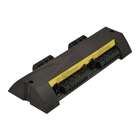
- Page 6 1039/501 1039/501 PIO Door Controller PIO Door Controller PIO Door Controller Reader 1 Reader 2 HOLD HOLD DATA DATA DATA Jumper functions Jumper functions...
- Page 7 The PIO Door Controller can be used with many types of Wiegand reader The PIO Door Controller can be used with many types of Wiegand reader The PIO Door Controller can be used with many types of Wiegand reader The PIO Door Controller can be used with many types of Wiegand reader The PIO Door Controller can be used with many types of Wiegand reader The PIO Door Controller can be used with many types of Wiegand reader The PIO Door Controller can be used with many types of Wiegand reader, and supply...
- Page 8 1039/534 1039/534 Expansion Card Expansion Card Expansion Card CT- CT+ BP- Reader 3 Reader 3 Reader 4 Reader 4 HOLD HOLD DATA DATA Note - screws must be screws must be used to ensure a good used to ensure a good electrical connection electrical connection between the 1039/501...
- Page 9 Connections between 1039/501, 1039/TCP/IP and 12V DC power supply 1039/501 Note – To test the electrical connections of the electric releases/magnetic locks, a Ethernet commissioning mode is available. connection By leaving the Ethernet connection 1039/MOD/IP unplugged the controller is automatically put into commissioning mode and will allow un-programmed keys to operate.
-
Page 10: 1104/451 451 - 13.56 Mhz
The 1104/451 Wiegand reader is used in the 1039/ The 1104/451 Wiegand reader is used in the 1039/ The 1104/451 Wiegand reader is used in the 1039/ The 1104/451 Wiegand reader is used in the 1039/19 IPervoice Elekta call module IPervoice Elekta call module IPervoice Elekta call module... -
Page 11: 1104/452 - 13.56 Mhz 34
The 1104/452 Wiegand reader is used in the 1039/ Wiegand reader is used in the 1039/ Wiegand reader is used in the 1039/13 IPervoice Elekta Glass call module Wiegand reader is used in the 1039/ 13 IPervoice Elekta Glass call module... -
Page 12: 1104/453 - 13.56 Mhz 34
1104/45 1104/453 – 13.56 MHz 34 13.56 MHz 34 13.56 MHz 34-bit Wiegand Wiegand OEM OEM reader connections reader connections reader connections HOLD HOLD CLK DATA Reader channel 1 or 2 of 1039/501 or Reader channel 1 or 2 of 1039/501 or Reader channel 1 or 2 of 1039/501 or Reader channel 1 or 2 of 1039/501 or reader channel 3 or 4 of 1039/534... -
Page 13: 1104/461
1104/461 & 1104/462 1104/461 & 1104/462 1104/461 & 1104/462 – 13.56 MHz 34 13.56 MHz 34 13.56 MHz 34-bit Wiegand ‘P60’ reader connections bit Wiegand ‘P60’ reader connections bit Wiegand ‘P60’ reader connections bit Wiegand ‘P60’ reader connections bit Wiegand ‘P60’ reader connections HOLD DATA Reader channel 1 or 2 of 1039/501 or... -
Page 14: 1104/431 - 13.56 Mhz 34
1104/4 1104/431 – 13.56 MHz 34 13.56 MHz 34 13.56 MHz 34-bit Wiegand mullion Wiegand mullion Wiegand mullion reader connections reader connections reader connections HOLD DATA Reader channel 1 or 2 of 1039/501 or Reader channel 1 or 2 of 1039/501 or Reader channel 1 or 2 of 1039/501 or Reader channel 1 or 2 of 1039/501 or reader channel 3 or 4 of 1039/534... -
Page 15: 1104/441 - 868 Mhz 34
1104/441 1104/441 – 868 MHz 34 868 MHz 34-bit Wiegand bit Wiegand bit Wiegand RF reader connections RF reader connections RF reader connections HOLD DATA Reader channel 1 or 2 of 1039/501 or Reader channel 1 or 2 of 1039/501 or Reader channel 1 or 2 of 1039/501 or Reader channel 1 or 2 of 1039/501 or reader channel 3 or 4 of 1039/534... - Page 16 Mounting The receiver is supplied in a plastic enclosure measuring 70mm wide x 60mm high x 17mm deep and is suitable for indoor use. If the receiver is to be used outside it must be mounted in a suitable waterproof plastic enclosure. An external aerial with coaxial connection is available if required, to increase the receiving range of the RF key –...
- Page 17 If using button two (or button three or four of a four button RF key fob) If using button two (or button three or four of a four button RF key fob) If using button two (or button three or four of a four button RF key fob) If using button two (or button three or four of a four button RF key fob) If using button two (or button three or four of a four button RF key fob) If using button two (or button three or four of a four button RF key fob)
- Page 18 Typical connection details for a RF Typical connection details for a RF Typical connection details for a RF Typical connection details for a RF Typical connection details for a RF reader in an automation system in an automation system in an automation system in an automation system Automation system 'Start Input' Automation system 'Start Input'...
- Page 19 Typical connection details for a magnetic lock Typical connection details for a magnetic lock Typical connection details for a magnetic lock Typical connection details for a magnetic lock Typical connection details for a magnetic lock Typical connection details for a magnetic lock Seperate DC lock Seperate DC lock power supply...
- Page 20 Typical connection details for a fail secure electric release Typical connection details for a fail secure electric release Typical connection details for a fail secure electric release Typical connection details for a fail secure electric release Typical connection details for a fail secure electric release Typical connection details for a fail secure electric release Typical connection details for a fail secure electric release Seperate DC lock...
- Page 21 Notes …………………………………………………………………………………………………………………………………………………………… …………………………………………………………………………………………………………………………………………………………… …………………………………………………………………………………………………………………………………………………………… …………………………………………………………………………………………………………………………………………………………… …………………………………………………………………………………………………………………………………………………………… …………………………………………………………………………………………………………………………………………………………… …………………………………………………………………………………………………………………………………………………………… …………………………………………………………………………………………………………………………………………………………… …………………………………………………………………………………………………………………………………………………………… …………………………………………………………………………………………………………………………………………………………… …………………………………………………………………………………………………………………………………………………………… …………………………………………………………………………………………………………………………………………………………… …………………………………………………………………………………………………………………………………………………………… …………………………………………………………………………………………………………………………………………………………… …………………………………………………………………………………………………………………………………………………………… …………………………………………………………………………………………………………………………………………………………… …………………………………………………………………………………………………………………………………………………………… …………………………………………………………………………………………………………………………………………………………… …………………………………………………………………………………………………………………………………………………………… …………………………………………………………………………………………………………………………………………………………… …………………………………………………………………………………………………………………………………………………………… …………………………………………………………………………………………………………………………………………………………… …………………………………………………………………………………………………………………………………………………………… …………………………………………………………………………………………………………………………………………………………… ……………………………………………………………………………………………………………………………………………………………...
Need help?
Do you have a question about the IPervoice and is the answer not in the manual?
Questions and answers