Table of Contents
Advertisement
Quick Links
Safety Operation and Maintenance Manual
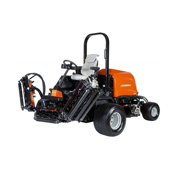
Jacobsen F305 & F407 Ride on Reel Mower
with KUBOTA - V1505-CR-TE5
Fairway F305
Product code: 10011560
Series: AAA
Fairway F407
Product code: 10011568
Series: AAB
WARNING: If incorrectly used this machine can cause severe injury. Those who use and maintain this
machine must be trained in its proper use, warned of its dangers and must read the entire manual before
attempting to set up, operate, adjust or service the machine.
WARNING
GB
United
Kingdom
10033001-A-GB
RJL AGCB
Advertisement
Table of Contents

Subscribe to Our Youtube Channel
Related Manuals for Jacobsen F305


Summary of Contents for Jacobsen F305
- Page 1 Safety Operation and Maintenance Manual Jacobsen F305 & F407 Ride on Reel Mower with KUBOTA - V1505-CR-TE5 Fairway F305 Product code: 10011560 Series: AAA Fairway F407 Product code: 10011568 Series: AAB WARNING WARNING: If incorrectly used this machine can cause severe injury. Those who use and maintain this machine must be trained in its proper use, warned of its dangers and must read the entire manual before attempting to set up, operate, adjust or service the machine.
-
Page 2: Table Of Contents
Cutting Units I/O Screen........35 Engine: Alternator Belt ........67 Cutters I/O Screen..........36 Engine Coolant............ 67 Traction I/O Screen ..........37 Hydraulic System ..........69 Main Controller Misc. I/O Screen ......38 Hydraulic System Flushing........70 © Ransomes Jacobsen Limited. All Rights Reserved... - Page 3 1 CONTENTS Hydraulic Test Ports ..........70 Seat (Grammer Msg85) ........89 Hydraulic Filter ............ 71 Air Suspension Seat (Grammer Msg75 -521) ..90 Fuel ..............72 8.10 Fuel System ............72 Accessories 8.11 Water System............73 10.1 Rear Roller Brush Kits ........93 8.12 Air Cleaner ............
-
Page 4: Introduction
2 INTRODUCTION IMPORTANT __________________________________________________________ The Jacobsen F305 & F407 are Diesel engined self propelled Reel mowers. The hydraulic systems are for the traction drive, the cutting unit lift and the lower and cutting unit drives and steering. IMPORTANT: Do the maintenance indicated in this manual to make sure that the quality of cut is kept at a high level. -
Page 5: Product Identification
INTRODUCTION 2 PRODUCT IDENTIFICATION ___________________________________________ Maximum front axle load in Kg (for machines being driven on the highway) West Road Ransomes Europark Gross weight (mass) in Kg Ipswich IP3 9TT England Maximum rear axle load in Kg (for machines being driven on the highway) Power in Kw Date code... - Page 6 The engine serial number is also found on the engine block. XXXXX-XXXXX Code No.: M A D E I N J A PA N ROPS Serial Plate Ransomes Jacobsen Ltd West Road Ransomes Europark Weight of ROPS Ipswich IP3 9TT...
-
Page 7: Guidelines For The Disposal Of Scrap Products
If an item is not easily separated into different material groups, the material must be added to the “General discarded materials” area. • Do not burn discarded materials. Change the machinery records to show that the machine is not in service and is discarded. Supply this serial number to Jacobsen Warranty Department to close their records. en-7... -
Page 8: Parts Manual
2 INTRODUCTION PARTS MANUAL ______________________________________________________ In compliance with the ISO14001 standard, Jacobsen Limited does not send a paper parts manual with every product. To refer to a parts list for this mower you have four options: Website – www.Jacobsen.com. Select the “SUPPORT” tab. You now have access to Parts drawings and lists to help with the identification of spare parts. - Page 9 INTRODUCTION 2 en-9...
-
Page 10: Safety
Know the location and correct operation of controls. Operators without experience must receive instruction from another person that knows the correct operation of the equipment before you operate the mower. Only use parts, accessories and attachments approved by Jacobsen Limited. 3.1.1 SAFE OPERATION ___________________________________________________ Read the Operator’s Manual and other training material. -
Page 11: Operation
SAFETY 3 Inspect the area where the equipment is operated. Remove all objects you can find before you operate. Be careful of obstructions above the ground (low tree limbs, electrical wires) and also underground obstacles (sprinklers, pipes, tree roots). Enter a new area carefully. Look for possible hazards. Inspect the cutting system before you start the mower. -
Page 12: Rops
Do not weld, drill, change or bend the structure. Replace a damaged ROPS. Do not try to correct a damaged ROPS frame. Do not remove the ROPS from the mower other than for maintenance access. Ensure to refit before use. Jacobsen must approve any changes to the ROPS. 3.1.5 SAFE HANDLING OF FUELS __________________________________________ The fuel and the fuel vapors are flammable. -
Page 13: When You Put The Mower On A Trailer
DO NOT operate the machine if you have worn or damaged parts for safety. Replace damaged or worn decals. Only use parts, accessories and attachments approved by Jacobsen. To decrease the fire hazard, remove materials that burn from the engine, muffler, battery tray and fuel tank area. -
Page 14: Important Safety Notes
By following all instructions in this manual, you increase the life of your machine and keep its maximum performance. Adjustments and maintenance must always be done by an approved technician. If a service is needed contact your authorized Jacobsen Dealer or after sales for additional information or help. en-14... - Page 15 2006/42/EC Sections 3.2.2, Seating & 3.4.3, Rollover. (ANSI B71.4-2012 section 20.7) Ransomes Jacobsen Limited recommends that the owner/user of the machine completes a site specific risk assessment of the machine to find any conditions that do not follow this rule.
- Page 16 3 SAFETY WARNING Vibration Exposure Limits Exposure limits are calculated as a combination of the vibration level (magnitude) of the tool and the Daily Exposure Time (Trigger Time). e.g. A product with 5m/s² vibration can be used up to 2 hours/day to reach the EAV and up to 8 hours/day to reach the ELV.
-
Page 17: Specification
SPECIFICATIONS 4 ENGINE SPECIFICATIONS _____________________________________________ Model: V1505-CR-TE5 (EPA/CARB Tier4 + EU Stage Type: Vertical, water cooled 4-cycle diesel engine Number of Cylinders Bore & Stroke mm (in.) 78.0 x 78.4 (3.07 x 3.09) Total Displacement L(Cu in.) 1.498 (91.41) Combustion Chamber Direct injection type Rated output / kW / min (rpm) -
Page 18: Dimensions And Weights
Wheel Track Rear - Measured Outer face to Outer face 199cm 78.3“ Turning Circle Outside Diameter 740cm 291.3“ Weight of Machine, F305 with ROPS. No Fuel, No Units (yokes only) 1230kg 2712lb Weight of Machine, F407 with ROPS. No Fuel, No Units (yokes only) 1413kg 3115lb... - Page 19 SPECIFICATIONS 4 F407 F305 F407 illustrated for reference. en-19...
-
Page 20: Machine Specification - Tires
66 cuts per metre at 12km/hr with 11 knife reels. 42 cuts per metre at 12km/hr with 7 knife reels. F407 4.32 hectares/hr.at 12kph (7.5mph) F305 3.17 hectares/hr.at 12kph (7.5mph) 10% allowance is included for normal overlaps and turning at the end of each cut. en-20... -
Page 21: Vibration
Referenced to Hand/Arm: BS EN ISO20643:2008 Information Supplied for Physical Agents Directive 2002/44/EC By reference to: Hand/Arm Standards: BS EN ISO 5349-1 (2001) BS EN ISO 5349-2 (2002) F305 Series AAA with ROPS Hand / Arm Max. LH or RH Accelerations m/s² Acceleration... -
Page 22: Noise
F407 Measured Sound Power 98.7dB(A) ± 1.24 LWA SLOPES ____________________________________________________________ F305 – DO NOT USE ON SLOPES GREATER THAN 24°. This slope was calculated using static stability measurements according to the requirements of BS EN ISO 5395 F407– DO NOT USE ON SLOPES GREATER THAN 23°. This slope was calculated using static stability... -
Page 23: Decals
Caution, Diesel Fuel. 4118415 Caution, Engine Coolant Under Pressure. 009034890 Keep A Safe Distance From The Machine. 009114160 Maximum Working Slope 24° F305. 4321507 Maximum Working Slope 23° F407. 009114100 Danger Of Explosion If The Battery Terminals Are Short Circuited. 009034930 Prevent Contact With Hydraulic-Oil Release Under Pressure. -
Page 24: Instruction Decals Ec
DECALS 5.2 INSTRUCTION DECALS ________________________________________________ CLASSIFICATION CJ-4 Beacon Parking Brake Horn Cutting Implement PTO Drive Throttle Traction Pedal, Forward / Reverse Power socket 12 volt Mow / Transport lever Maximum Sound Power Level Jack & Hook Point Engine Oil Classification en-24... -
Page 25: Controls 6
CONTROLS 6 OPERATOR WORKSTATION____________________________________________ 6.12 6.10 6.16 6.2A en-25... -
Page 26: Control Panel
6 CONTROLS CONTROL PANEL ___________________________________________________ Not In Use F407 F305 Starter Key Switch Centre Cutting Units Lift/Lower Control Throttle Control Cutting Units Position Indicator Lamp Park Brake Switch Cutters (PTO) Indicator Lamp Cutter Switch (PTO) Right Hand Wing Cutting Unit Position Lamp... -
Page 27: A Starter Key Switch
CONTROLS 6 6.2.A STARTER KEY SWITCH_______________________________________________ The Starter Key (A) must be turned clockwise to the 'start' position to start the engine. After starting, the key must be released and allowed to return automatically to the 'on' position for normal running. NOTE:The glow plugs will auto pre-heat depending on the coolant temperature before cranking begins. -
Page 28: E Light Switch (Optional)
6 CONTROLS 6.2.E LIGHT SWITCH (OPTIONAL)___________________________________________ Switches the road lights on and off. Position 1. OFF Position 2. Front Only Position 3. Front / Rear NOTE: Position 3 requires ignition to be on. 6.2.F WING LOCK SWITCH_________________________________________________ Engages the Wing Cutting Unit lift arm locks for transport, preventing un- intentional lowering of the cutting units whilst driving. -
Page 29: Service Warning Screen
CONTROLS 6 6.3.2 WARNING / SERVICE SCREEN_________________________________________ After the Start-up Screen the Warning Screen is shown, the screen is visible for four seconds. If the machine is within 5 hours of the next service, a warning is shown. An operator input is needed to continue to the Home Screen. -
Page 30: Home Screen
6 CONTROLS 6.3.3 HOME SCREEN _____________________________________________________ The Home Screen will give the operator alternative button functions when Button 4 has been pressed once 02:01 3.4 Hours Buttons numbered left to right: ® Button 1:DPF Regen Start Button 2:DPF Regen Inhibit *Note - Refer to section 8.16 Diesel Particulate filter for full details. -
Page 31: Main Menu
CONTROLS 6 6.3.6 MAIN MENU ________________________________________________________ The arrow is moved up and down using Button 2 and 3, Button 4 then enters the selected page, Button 1 returns to the Home Screen. There will be four options within this menu: Main Menu Clock Service Menu... -
Page 32: Fault Log
6 CONTROLS FAULT LOG _________________________________________________________ The first page within the Fault Log makes it possible to see any Fault Popup Warnings that have occurred and been cleared, that are however still active. Button 2 & 3 can be used to scroll through if there is more than one, Button 1 exits to the Service Menu. -
Page 33: I/O Diagnostics
CONTROLS 6 Engine Speed Engine Throttle Postion Cutter Hours Fuel Level Engine Total Fuel Used Engine Fuel Rate 0.0V 0% R.P.M. Volt - % R.P.M. Litre Pedal A Position Pedal B Position Engine Coolant Temperature Battery Voltage DPF Soot Engine Torque 0.0V 0% 0.0V 0% 12.0... -
Page 34: General I/O Screen
Engine Ignition Key Input Main Controller c1p10 Park Brake Switch Input Main Controller c1p19 Hydraulic Oil Level Switch Input Not used on F305/F407 Main Controller c1p31 Engine Run Interlock Output Expansion Module c2p03 Reverse Beeper Output Not used on F305/F407... -
Page 35: Cutting Units I/O Screen
CONTROLS 6 Cutting Units Ref Module Function Note Number c1p09 Left Hand Joystick Input Not used on F305 Main Controller c1p16 Left Hand Position Sensor Input Not used on F305 Expansion Module c2p04 Left Hand Float Solenoid Output Not used on F305... -
Page 36: Cutters I/O Screen
Pin Number Function Note c1p07 Cutter Switch (PTO) Input Main Controller c1p18 Wing Disable Switch Input Not used on F305 Main Controller c1p40 Left Hand Cut Solenoid Output Not used on F305 Expansion Module c2p06 Left Hand Transport Lock Solenoid... -
Page 37: Traction I/O Screen
CONTROLS 6 Traction Module Pin Number Function Note Main Controller c1p07 Cutting Circuit Pressure Switch Input Not used on F305/F407 Main Controller c1p24 Right Hand Wheel Speed Sensor Not used on F305/F407 Input Main Controller c1p27 Traction Pedal Signal B Input... -
Page 38: Main Controller Misc. I/O Screen
6 CONTROLS Main Controller Miscellaneous Pins Module Pin Number Function Note Main Controller c1p01 Battery Negative Main Controller c1p04 CAN 0 Low Main Controller c1p09 Sensor Power Ground Main Controller c1p22 CAN 1 Shield Main Controller c1p49 Battery Positive Main Controller c1p02 Battery Positive Main Controller... -
Page 39: Misc.continued I/O Screens
CONTROLS 6 Miscellaneous Pins Continued Module Pin Number Function Note Expander Module c1p01 Battery Negative Not used on F305 Expander Module c1p04 CAN 0 Low Not used on F305 Expander Module c2p11 Battery Positive Not used on F305 c1p01 Battery Negative... -
Page 40: Pin Menu
After 2 minutes of continued use in Cross Cut the PTO will have to be manually reactivated using the PTO switch. Cross cut function on the F305 is mechanically controlled via a foot oper- ated lever (A) on the Operator Platform. The units will only lift to cross cut position unless this lever is pressed, enabling the units to fully lift. -
Page 41: Weight Transfer
CONTROLS 6 6.5.8 WEIGHT TRANSFER _________________________________________________ Weight transfer function transfers ground pressure between the cutting units and the road wheels, giving either optimal ground following of units or increased traction at the wheels. Weight Transfer can be selected from Weight Transfer the Settings menu (Section.6.5.4), and then Enabled or Disabled within Disabled Enabled... -
Page 42: Brightness Screen Adjustment
6 CONTROLS 6.5.11 BRIGHTNESS _______________________________________________________ Using the PIN Menu Buttons 2 and 3 to arrow down to the bottom of the list, and Button 4 to select Brightness, this gives you the option to change from day to night mode. Brightness 100% The top line is used to alter the brightness in daytime mode. -
Page 43: Warning Oil Pressure Fault
1000 rpm. Stop the engine and check the oil level. Top up if necessary. If the fault persists, do not use the machine at all and contact your local Ransomes Jacobsen dealer. 6.6.2 WARNING ENGINE OVERHEAT ________________________________________ When this screen is shown, the engine... -
Page 44: Warning Charge Filter Blocked
When this screen is shown, the engine controller (ECU) is reporting an abnormal DPF Differential Pressure or a fault with the sensor itself. The output from the engine may be reduced. Stop the engine as soon as pos- sible and contact your local Ransomes Jacobsen Dealer. en-44... -
Page 45: Emission Fault Egr Nox Control
EMISSION FAULT - DPF SENSOR __________________________________ When this screen is shown, the engine controller (ECU) is reporting a fault with the DPF (Diesel Particulate Filter). Stop the engine as soon as possible and contact your local Ransomes Jacobsen Dealer. SENSOR en-45... -
Page 46: Clean Dpf Ash
When this screen is shown, the engine controller (ECU) is reporting that the level of ash in the DPF (Diesel Particulate Filter) is in excess of 95% and therefore the DPF needs to be serviced. Contact your local Ransomes Jacobsen Dealer for information on the procedure for servicing the DPF. >95% 6.6.12... -
Page 47: Cutting Unit Lift/Lower
To lift or lower the Cutting Units, the machine must first be set to Mow Mode by moving the Mow Speed Lever into Mow position. (Section.6.11). F305 The Cutting Unit Lift / Lower control lever will raise and lower all cutting units simultaneously. -
Page 48: Cutting Unit Position/Mode Lamp
The lamps (M) illuminate green when the Cutting Units are lowered to the ground. F407 F305 F407 only - When Linked Lift Mode is activated (Section.6.7), the Left and Right control Lever LED indicators will illuminate Red to indicate that the respective levers are disabled. -
Page 49: Traction Pedal
CONTROLS 6 6.10 TRACTION PEDAL____________________________________________________ The traction pedal is found on the right side of the footplate. • Carefully press the top (A) of the foot pedal to reach the forward speed that you need. • To stop - Carefully return the foot pedal to the Neutral position. •... -
Page 50: Power Outlet
6 CONTROLS 6.13 POWER OUTLET _____________________________________________________ The auxiliary power outlet is on the side of the control panel. It is for use with mobile phone chargers and accessories. Automotive 12 Volt, 10 Amp power outlet. 6.14 PARK BRAKE RELEASE VALVE ________________________________________ The Park Brake Release Valve is situated under the seat plate, on the right hand chassis plate. -
Page 51: Seat Arm Rest & Pod
CONTROLS 6 WARNING THE FREE WHEEL FACILITY IS FOR RECOVERY PURPOSES ONLY. DO NOT TOW THE MACHINE FOR MORE THAN A FEW METRES, OR ALLOW THE MACHINE TO FREE WHEEL DOWN SLOPES EVEN WHEN UNLOADING DOWN RAMPS. 6.16 SEAT RIGHT HAND ARM REST & POD ___________________________________ The right hand arm rest of the seat has an extension mounted to it which carries the control pod. -
Page 52: Operation
7 OPERATION DAILY INSPECTION_________________________________________________ CAUTION The daily inspection should be performed only when the engine is off and all fluids are cold. Lower units to the ground, engage Park Brake, stop engine and remove Ignition Key. 1. Perform a visual inspection of the entire machine, look for signs of wear, loose hardware and missing or dam- aged components. -
Page 53: Operating Procedure
OPERATION 7 Cutter Engage Test Operator Seated Traction Pedal Park Brake Switch Engine Starts (PTO) Switch Out of Neutral Neutral Lift your weight off the seat. The cutting implement PTO will disengage within 3 seconds. Lift your weight off the seat. The engine must stop after 3 seconds. OPERATING PROCEDURE ___________________________________________ WARNING Never operate the equipment with the operator presence... -
Page 54: Fitting The Cutting Unit To The Machine
7 OPERATION FITTING CUTTING UNIT _____________________________________________ Cutting Unit Mounting 1. Start the engine and lower the lift arms, stop engine and remove ignition key. 2. Position cutting unit under lift arm. Apply thin coating of grease to shaft and slide yoke onto shaft in direction 3. -
Page 55: Operation Of The Machine
OPERATION 7 LH = Left Hand Drive RH = Right Hand Drive OPERATION OF THE MACHINE _______________________________________ Read the Safety Instructions. BEFORE OPERATING FOR THE FIRST TIME • Check and adjust tires pressure, if necessary, see section 4.4 Specification. • Add diesel fuel to tank if necessary. -
Page 56: Driving
7 OPERATION DRIVING __________________________________________________________ • Release brake - Make sure the Park Brake is released before attempting to go forward or reverse. • Forward - Gently depress the top of the FWD/REV foot pedal to reach desired ground speed. • Reverse - Gently depress the bottom of the FWD/REV foot pedal to reach desired ground speed. •... -
Page 57: Backlapping
• Backlapping must only be done by approved personnel. • Jacobsen recommend that backlap paste is only applied to the reel when it is stationery, the engine is off and the parking brake applied. • When applying backlap paste the reel must only be rotated by appropriately sized piece of wood and not by hand. -
Page 58: Procedure
3.3 – Adjusts the Right Hand Wing Unit F305 - There is a single hand wheel adjustment screw on top of the cutter valve. To adjust the speed, select the required valve screw, Back off the lock nut (A). Screw the Hand wheel (B) Clock- wise to decrease reel speed or counter-clockwise to increase reel speed. -
Page 59: Transporting On A Trailer Or Flat-Bed
TRANSPORTATION ON A TRAILER OR FLATBED________________________ 1. Jacobsen advises securely fastening the front of the mower down by either strapping over the front axle or the road wheels using suitable equipment. The tie-down loops at (A) are for securing the rear of the machine. -
Page 60: Mowing On Slopes
ROPS to comply with the Machinery Directive 2006/42/EC sections 3.2.2, Seating & 3.4.3, Roll-over Ransomes Jacobsen Limited recommends that a local risk assessment is completed by the owner/user of the machine to determine the risks associated with working on slopes. -
Page 61: Maintenance And Lubrication 8
MAINTENANCE AND LUBRICATION 8 MAINTENANCE & LUBRICATION CHART__________________________________ GENERAL MAINTENANCE AND LUBRICATION CHART Interval Item Section First 50 hours Visual inspection for damage or wear Check reel & bottom blade condition Change Hydraulic Charge Filter Element or earlier if screen indicates. - Page 62 8 MAINTENANCE AND LUBRICATION 8.13 F405 Illustrated. Service points are common for F305. en-62...
-
Page 63: Engine Service Interval Chart
MAINTENANCE AND LUBRICATION 8 8.1.1 ENGINE SERVICE INTERVAL _______________________________________________ ENGINE SERVICE INTERVAL CHART Interval Item Section Daily 8.2.1 Check engine oil level. 10 hours Check fuel level. 6.3.4 Check coolant level. Check alternator belt tension. Press together the air cleaner dust valve. - Page 64 8 MAINTENANCE AND LUBRICATION Interval Item Section Replace oil separator related rubber piping. Replace DPF related rubber piping. Replace intake air line and suction air pressure takeout rubber piping. Replace boost sensor pressure rubber piping. Replace EGR cooler rubber piping.
-
Page 65: Engine Service General
The operation and maintenance during the first 50 hours of a new engine can make a difference to the performance and life of the engine. During the first 50 hours of operation, Jacobsen recommends the following. • Allow the engine to reach a temperature of at least 60° C (140° F) before operation at full load. -
Page 66: Engine Lubrication Check
8 MAINTENANCE AND LUBRICATION 8.2.1 ENGINE LUBRICATION ______________________________________________ Check Engine Oil Level Check the engine oil level before you start or at least five minutes after you stop the engine. Park the machine on level ground, remove the dipstick (A), clean with a cloth and replace in position. -
Page 67: Engine Alternator Belt
MAINTENANCE AND LUBRICATION 8 ENGINE ALTERNATOR BELT ___________________________________________ Check and adjust the alternator belt The alternator belt tension is adjusted to prevent the stress on the alternator bearings and to prevent movement on the alternator pulley. Use the procedure shown below to check the belt tension at the center of the belt between crank shaft and alternator pulleys. - Page 68 Check and tighten the engine fan belt and replace the belt, clamps and hoses (see maintenance chart). Have your Jacobsen Dealer check the cooling system if you need to add coolant more than one time a month or you add more than a litre of coolant at a time.
-
Page 69: Hydraulic System
MAINTENANCE AND LUBRICATION 8 HYDRAULIC SYSTEM __________________________________________________ Drain and replace the hydraulic oil if one of the following occur. • Component failure • Water or foam is in the hydraulic fluid • The hydraulic fluid has a rancid odour (indication of high heat) •... -
Page 70: Hydraulic System Flushing
All tests, unless stated otherwise, must be carried out with the hydraulic oil at normal working temperature. TEST PORT Return Manifold Test Port - Located under operators platform on forward bulkhead. NOTE: Any hydraulic related issues contact your Jacobsen dealer for a full fault diagnosis. en-70... -
Page 71: Hydraulic Filter
MAINTENANCE AND LUBRICATION 8 HYDRAULIC FILTER ___________________________________________________ The hydraulic system is protected by a 10 micron filter (A). Flow through the filter is monitored while you operate the mower. When the difference in hydraulic pressure across the filter is greater than 16 to 20 psi (1.1 to 1.4 BAR), the hydraulic oil filter warning light on the combination gauge will illuminate. -
Page 72: Fuel
8 MAINTENANCE AND LUBRICATION FUEL________________________________________________________________ Diesel fuel is flammable. Use caution when you add the fuel to the mower. Only use an approved container. The spout on the container must fit inside the fuel filler neck. Never use the containers that are not approved to keep or transfer fuel. -
Page 73: Water System
MAINTENANCE AND LUBRICATION 8 8.11 WATER SEPARATOR___________________________________________________ If water is not removed from the fuel, damage to the fuel-injection system can occur. When water in fuel icon is displayed or at service interval, drain the water from the water separator. Stop the engine. -
Page 74: Air Cleaner
8 MAINTENANCE AND LUBRICATION CAUTION Discard diesel fuel in accordance with Local Authority Regulations 8.12 AIR CLEANER ________________________________________________________ Check the service indicator (F) each day. If the red band become visible in the window, replace the filter elements. Check the dust valve (A) each day by pressing the valve together allowing any dust particles to fall out of the air cleaner cover. -
Page 75: Battery
MAINTENANCE AND LUBRICATION 8 8.13 BATTERY ____________________________________________________________ Before you service the battery, make sure the ignition switch is in the OFF position and the key is removed. CAUTION When you service the battery, always use the tools with insulation, wear protective glasses and protective clothing. -
Page 76: Battery Charging
8 MAINTENANCE AND LUBRICATION 8.14 BATTERY CHARGING _________________________________________________ Read the battery charger manual for specified instructions on the operation of the charger. WARNING Charge the battery in an area with good airflow. The battery can release hydrogen gas that is explosive. To prevent an explosion, keep any device that can cause sparks or flames away from the battery. -
Page 77: Diesel Particulate Filter
MAINTENANCE AND LUBRICATION 8 8.16 DIESEL PARTICULATE FILTER __________________________________________ During operation of the mower, the level of particle material will increase in the Diesel Particulate Filter (DPF) system. The periodic Regen of the DPF system is needed to remove particle material. During an Active or Parked Regen, the engine will use more fuel. -
Page 78: Hydraulic Hoses
8 MAINTENANCE AND LUBRICATION 8.17 HYDRAULIC HOSES __________________________________________________ WARNING To prevent injury from the hot, high pressure oil, never use your hands to check for oil leaks. Use paper or cardboard to find leaks. The hydraulic fluid pressure can have enough force to enter your skin. If hydraulic fluid has entered your skin, please seek medical attention as soon as possible. -
Page 79: Wheel Mounting Procedure
MAINTENANCE AND LUBRICATION 8 8.19 WHEEL MOUNTING PROCEDURE _______________________________________ WARNING Make sure the mower is parked on a solid and level surface. Never work on a mower that is supported only by the Jack. Always use Axle Stands. If only the front or rear of the mower is lifted, put the chocks in front of and behind the wheels that are not lifted. -
Page 80: Steering Rod & Link Check
8 MAINTENANCE AND LUBRICATION 8.21 STEERING ROD AND STEERING LINK CHECK _____________________________ The rear axle must be adjusted for 1/16 inch (1.6 mm) toe-in. Turn the rear wheels to the straight position. Loosen the jam nuts (B) on both ends of the tie rod (A). -
Page 81: Rops
The Machinery Directive, 2006/42/EC sections 3.2.2, seating & 3.4.3, rollover. (ANSI B71.4-2012: Sect;20.7) Ransomes Jacobsen Limited, recommend that the owner operator of the machine complete site specific risk assessment on the machine to find any conditions that do not follow this rule. -
Page 82: Lubrication Of Cutting Unit
8 MAINTENANCE AND LUBRICATION 8.24 LUBRICATION OF CUTTING UNITS _______________________________________ Cutting reel bearings (A). Unit Pivot (B. Roll Bearings (C) REEL ON CUT ADJUSTERS If the adjusters are removed from the machine, the adjuster must be half filled with gear oil EP90. HYDRAULIC MOTOR DRIVE SHAFT (EVERY 200 HOURS) Lower all cutting units down to ground level. - Page 83 MAINTENANCE AND LUBRICATION 8 en-83...
-
Page 84: Adjustments
“bounce” on undulating ground. It is recommended that the Allen key B is turned a 1/4 turn at a time and the weight transfer tested. Tighten locknut A. whilst holding the threaded shaft still with the Allen Key B. DO NOT OVERTIGHTEN. F305 F407 en-84... -
Page 85: Cutting Unit - Setting Height Of Cut
ADJUSTMENTS 9 CUTTING UNIT - SETTING HEIGHT OF CUT _______________________________ First set the rear roll parallel to the bottom blade (bedknife). Set the minimum-height of cut setting for the three ranges of height. Adjust the setting with the three sets of holes in the mounting housing (D) at positions 'A', 'B' and 'C'. -
Page 86: Cutting Reel To Bottom Blade Adjustment
9 ADJUSTMENTS CUTTING REEL TO BOTTOM BLADE ____________________________________ Make sure that the cutting reel is installed in position with the bottom blade correctly. Hold a piece of thin paper between the edge of the blade and the spiral cutters and turn the reel manually. If the cut on the paper is smooth along the full length of the bottom blade, then the adjustment is correct. -
Page 87: General Instructions For Grammer Seats
ADJUSTMENTS 9 GENERAL INSTRUCTIONS FOR GRAMMER SEAT _________________________ • The operating instructions must be read in full before use. • The driver’s seat may only be fitted, serviced and repaired by specialist personnel, In accordance with national regulations and the vehicle manufacturer’s fitting instructions. •... - Page 88 9 ADJUSTMENTS After removal of the backrest upholstery, the backrest frame must be supported, for example held in place, before the backrest adjuster is operated. If you fail to do so, there is a danger that the backrest frame may jerk forward and cause injury.
-
Page 89: Seat (Grammer Msg85)
ADJUSTMENTS 9 SEAT (GRAMMER MSG85) _____________________________________________ WARNING The Operator weight must be set to the actual weight of the Operator. Safety Systems will be compromised if this is not done. The seat can be adjusted for operator's weight and leg reach to provide a comfortable position for operating the machine. -
Page 90: Air Suspension Seat (Grammer Msg75-521)
9 ADJUSTMENTS AIR SUSPENSION SEAT (GRAMMER MSG75-521)__________________________ WEIGHT ADJUSTMENT The seat is adjusted for the driver’s weight by pulling or pressing the lever for seat weight adjustment and with the driver sitting on the seat. The driver’s weight is adjusted correctly when the arrow is in the middle clear area of the viewing window. - Page 91 ADJUSTMENTS 9 LUMBAR SUPPORT The lumbar support increases both the seating comfort and the performance of the driver. By turning the adjustment knob upwards, the curvature in the upper part of the backrest cushion can be adjusted. By turning the knob downwards, the curvature in the lower part of the backrest cushion can be adjusted.
- Page 92 9 ADJUSTMENTS BACKREST ADJUSTMENT Moving the locking lever upwards loosens the notching of the backrest adjustment. After the adjustment, the locking lever must latch into the desired position. It must not be possible to move the backrest into another position when it is locked. For an ergonomic use the backrest can be adjusted in a range of –5 to +30 degrees (15 steps of 2.5 degrees each).
-
Page 93: Accessories
10 ACCESSORIES 10.1 REAR ROLLER BRUSH KITS __________________________________________ Field Kit number: F305 - 10031704-F30-5-F F406 - 10031704-F40-7-F Factory Fit: F305 - 10031704-F30-5-P F406 - 10031704-F40-7-P 10.2 GRASS CATCHER KITS ______________________________________________ Grass Catcher Kit 26” Reel (5 Units) kit Number JMAB302. -
Page 94: Air Suspension Seat Kits
10 ACCESSORIES 10.3 AIR SUSPENSION SEAT KITS _________________________________________ Air Suspension Seat Kit for F305 Kit number LMAC201. Air Suspension Seat Kit for F407 Kit number LMAC277. 10.4 WORK LIGHT KIT __________________________________________________ Work Light Kit number 10013067 en-94... -
Page 95: Problem Solving 11
PROBLEM SOLVING 11 11.1 PROBLEM SOLVING GENERAL____________________________________ Symptoms Possible Causes Action Glow plug has not timed out Reset ignition switch and allow glow plug to time out before cranking engine. Battery low on charge or Inspect condition of battery and battery connections. defective. -
Page 96: Quality Of Cut
12 QUALITY OF CUT QUALITY OF CUT TROUBLESHOOTING_________________________________ Make a “test cut” to check the performance of the 1. Cut (Ground) Speed. mower before you start the repairs. This area must have turf conditions that are known 2. The Reel Bearing Condition And Adjustment and do not change across the area. -
Page 97: Marcelling
12 QUALITY OF CUT 12.2 MARCELLING______________________________________________________ Marcelling, like washboarding, is a repeated pattern of different cutting heights, that causes an appear- ance that is like a wave. In most cases, the wave tip-to-tip distance is 2 inch- es (5 cm). TN0220 NOTE: Arrow indicates direction of travel. -
Page 98: Step Cutting
12 QUALITY OF CUT 12.3 STEP CUTTING _____________________________________________________ Step cutting occurs when the grass is cut higher on one side of a reel than the other side. Step cutting can occur when one cutting unit is higher than anoth- er cutting unit. The wear of mechanical parts or an incorrect roller or height-of-cut adjustment can cause step cutting. -
Page 99: Scalping
12 QUALITY OF CUT 12.4 SCALPING ________________________________________________________ Scalping is a condition in which a areas of grass are cut shorter than the adjacent areas. The area can be light green or brown. A low height-of-cut (HOC) set- ting or turf that is not level can cause scalping. TN0222 NOTE: Arrow indicates direction of travel. -
Page 100: Stragglers
12 QUALITY OF CUT 12.5 STRAGGLERS ______________________________________________________ Stragglers are separated blades of grass that are not cut, or are cut incorrectly. TN0223 NOTE: Arrow indicates direction of travel. Possible Cause Solution The bedknife is incorrectly adjusted. Adjust reel-to-bedknife setting. The edges of the reel or bottom blade are not sharp. Sharpen or replace the reel blade and bedknife as necessary. -
Page 101: Streaks
12 QUALITY OF CUT 12.6 STREAKS _________________________________________________________ A streak is a line of grass that is not cut. The cause of a streak can be a damaged or bent bedknife. TN0224 NOTE: Arrow indicates direction of travel. Possible Cause Solution Damaged bedknife. -
Page 102: Windrowing
12 QUALITY OF CUT 12.7 WINDROWING ______________________________________________________ Windrowing is the deposit of clippings increased at one end of the cutting unit or between two cutting units. Windrowing can make a line in the direction of travel. TN0225 NOTE: Arrow indicates direction of travel. Possible Cause Solution The grass is higher than the level at which the ma-... -
Page 103: Rifling Or Tramlining
12 QUALITY OF CUT 12.8 RIFLING OR TRAMLINING ___________________________________________ Rifling or tramlining is a pattern of different cutting heights, that causes a cut appearance like a wave. The cause of rifling can be a heavy contact point across a reel or a bedknife. NOTE: Arrow indicates direction of travel. -
Page 104: Fuse And Relay/Component Identification
13 SCHEMATICS 13.1 ELECTRICAL FUSES & RELAYS____________________________________ Replacement Fuses Fuse Tester 5A 7.5A 10A 15A 20A 25 Fuse Removal Tool B/LAP SPARE ENGINE FLASHER IGNITION GLOW PLUGS START TESTING A FUSE In the top right hand corner there is a tool that can be used to remove a fuse from its location. The tabs on the fuse should then be inserted into the slots that can be seen in the top RH corner so that they touch the sides of the hole. - Page 105 SCHEMATICS 13 FUSE NO. RATING FUNCTION 40 Amp Glow Plugs 70 Amp Ignition On 7.5 Amp Hazard Lights (Optional) 10 Amp Starter 25 Amp Engine Master 5 Amp EGR Valve 7.5 Amp Fuel Pump 10 Amp Engine Sensors 20 Amp Engine Controller 5 Amp Engine Controller Start Signal...
-
Page 106: Torques
14 TORQUES TORQUES ______________________________________________________ FINE PITCH METRIC THREADS COARSE PITCH METRIC THREADS Grade Grade Grade Grade Grade Grade Grade Grade Grade Grade (mm) 10.9 12.9 (mm) 10.9 12.9 (Nm) (Nm) (Nm) (Nm) (Nm) (Nm) (Nm) (Nm) (Nm) (Nm) 1055 1266 1152 1327 1593... -
Page 107: Guarantee 15
GUARANTEE 15 GUARANTEE ___________________________________________________________ WARRANTY Warranty is subject to specific terms and conditions, e.g. wearing parts, unapproved modifications, etc. are not included. For a full set of warranty conditions, contact your local dealer or distributor. NOTICE The use of components not provided by the manufacturer under this warranty or maintenance or repair that is improperly or incorrectly performed may void this warranty. - Page 108 Health & Safety Management Cert No. FS609275 Cert No. EMS609276 Cert No. OHS609277 United Kingdom Ransomes Jacobsen Limited West Road, Ransomes Europark, Ipswich, IP3 9TT English Company Registration No. 1070731 T: +44 1473 270000 W: www.ransomes.com Europe office Ransomes Jacobsen France...
Need help?
Do you have a question about the F305 and is the answer not in the manual?
Questions and answers