Table of Contents
Advertisement
Quick Links
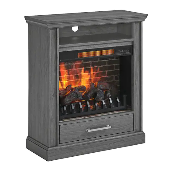
Item #1007512418
Model #2291FM-23-259
ASSEMBLY INSTRUCTIONS
HASWELL PETITE FOYER MANTEL IN CASHMERE
Questions, problems, missing parts?
Before returning to the store, call Home Decorators Collection Customer Service
8 a.m. - 7 p.m., EST, Monday - Friday, 9 a.m. - 6 p.m., EST, Saturday
1-800-986-3460
HOMEDEPOT.COM/HOMEDECORATORS
THANK YOU
We appreciate the trust and confidence you have placed in Home Decorators Collection through the purchase of this fireplace console. We strive
to continually create quality products designed to enhance your home. Visit us online to see our full line of products available for your home
improvement needs. Thank you for choosing Home Decorators Collection!
Advertisement
Table of Contents

Related Manuals for Home Decorators Collection 2291FM-23-259


Summary of Contents for Home Decorators Collection 2291FM-23-259
- Page 1 THANK YOU We appreciate the trust and confidence you have placed in Home Decorators Collection through the purchase of this fireplace console. We strive to continually create quality products designed to enhance your home. Visit us online to see our full line of products available for your home...
-
Page 2: Table Of Contents
Table of Contents Table of Contents ........2 Package Contents . - Page 3 Safety Information (continued) □ Use this appliance only as described in the manual. Any other use □ “WARNING – Death or serious injury may occur when children is NOT recommended by the manufacturer and may cause fire, climb on audio and/or video equipment furniture. A remote control electric shock or injury to persons.
- Page 4 Safety Information (continued) Electrical Connection Grounding Instructions □ A 15-Amp, 120-volt, 60 Hz circuit with a properly grounded □ This heater is for use on 120 volt. The cord has a plug as outlet is required. Preferably, the fireplace will be on a shown below.
-
Page 5: Warranty
Warranty The manufacturer warrants that your new electric fireplace is free from manufacturing and material defects for a period of one year from date of purchase, subject to the following conditions and limitations. Install and operate this electric fireplace in accordance with the installation and operating instructions furnished with the product at all times. -
Page 6: Pre-Installation
Pre-Installation PLANNING INSTALLATION Before beginning assembly of product, make sure all parts are present. Compare parts with package contents list and hardware contents list. If any part is missing or damaged, do not attempt to assemble the product. Estimated Assembly Time: 50 minutes. Tools Required for Assembly (not included): Phillips screwdriver. -
Page 7: Package Contents
Pre-Installation (continued) PACKAGE CONTENTS Part Description Quantity Left Wall Right Wall Front Panel Center Shelf Upper Back Panel Fireplace Brick Wall Fireplace Glass Front Fireplace Brick Bottom Wall Bottom Back Panel Left Side Panel Right Side Panel Fire Log Fireplace Grate Remote Control (Battery Inside) Drawer Left Panel Drawer Right Panel... -
Page 8: Installation
Installation Screw connecting rod □ Screw six connecting rods (CC) into the holes on the back of the front panels (D). Fully tighten with a Phillips screwdriver. Install L/R walls □ Insert two wooden dowels (BB) into holes on left wall (B). Align the holes on left wall (B) with the corresponding holes on front panel (D), secure with three locknuts (DD). - Page 9 Installation (continued) Screw connecting rod □ Screw four connecting rods (CC) into the holes on the back of the fireplace brick bottom wall (I). Fully tighten with a Phillips screwdriver. Install fireplace brick bottom wall □ Insert two wooden dowel (BB) into each side of fireplace brick bottom wall (I). Align the holes on fireplace brick bottom wall (I) with the corresponding holes on left wall (B), secure with two locknuts (DD).
- Page 10 Installation (continued) Install L/R side panels □ Insert four wooden dowels (BB) into holes on the back of the fireplace brick bottom wall (I). Align the holes on fireplace brick bottom wall (I) with the corresponding holes on left side panel (K), secure with two locknuts (DD). □...
- Page 11 Installation (continued) Install bottom back panel □ Attach bottom back panel (J) to drawer areas using twelve back panel screws (KK). Install fireplace glass front □ From behind the assembly, attach the fireplace glass front (H), lowering it into the front groove on fireplace brick bottom wall (I). □...
- Page 12 Installation (continued) Install center shelf □ Insert four short wooden dowels (OO) into the holes on both left wall (B) and right wall (C). □ Carefully position the center shelf (E) into place between left wall (B) and right wall (C). □...
- Page 13 Installation (continued) Install top □ Insert six wooden dowels (BB) into the top outer holes on both left wall (B) and right wall (C). Attach top (A), and secure with screwing four locknuts (DD) by Phillips screwdriver. Install upper back panel □...
- Page 14 Installation (continued) Install drawer panels □ Align the holes of drawer back panel (S) to the drawer left panel (Q) and the drawer right panel (R), secure with four drawer screws (HH). Install drawer bottom panel □ Insert the drawer bottom panel (T) into the groove of assembly from step 13.
- Page 15 Installation (continued) Screw connecting rod □ Screw four connecting rods (CC) into the holes on the back of the drawer front panel (U). Fully tighten with a Phillips screwdriver. Install drawer front panel □ Insert two small locknuts (EE) into the holes of left side and right side of drawer, secure with screwing the small locknuts (EE) by Phillips screwdriver.
- Page 16 Installation (continued) Install drawer pull □ Place drawer pull (LL) into predrilled hole on drawer front panel (U), securing with two drawer pull screws. Install drawer □ Slide glide roller (on track inside cabinet) to front. Carefully align drawer box glide track (attached to sides of drawer box) with glide track (attached to inside of cabinet).
- Page 17 Installation (continued) Install fireplace grate □ Place the fireplace grate (N) by matching the bottom pins into the holes on the fireplace brick bottom wall (I), secure with screwing two bolts (NN) by Phillips screwdriver. Install fire log □ Remove the film from the adhesive on the top of the fireplace grate (N) and place the fire log (M) on the center of the fireplace grate (N).
- Page 18 Installation (continued) Install L-bracket □ Screw two L-bracket (II) onto the fireplace brick wall (G) using four short screws (JJ). Install fireplace brick wall □ Attach the USB cable from the heater into the USB port behind the fireplace grate (N). □...
- Page 19 Installation (continued) WARNING: You must install the tip restraint hardware to help prevent any accidents or damage to the unit. We strongly recommend attaching the tip restraint hardware to a wall stud and your unit. For all other wall types, please visit your local hardware store to obtain the proper hardware.
-
Page 20: Operating Instructions
Operating Instructions Control Panel Remote Control To use the remote control, first remove the plastic tab by gently pulling it out of remote control. Controls and Display The control panel will display the heater setting when the unit power is turned ON. Whichever control icon you press will display the current setting of the corresponding function. - Page 21 Operating Instructions (continued) NOTE: This may not exactly match the room thermostat reading as their sensors are located in different areas. □ Hold down the FLAME SPEED ICON for 10 seconds to toggle between Fahrenheit and Celsius. “F” or “C” will be displayed on the control panel (°F/°C can only be toggled from the control panel and will not work if using the remote control).
-
Page 22: Care And Maintenance
Care and Maintenance □ Make sure the unit is turned OFF, unplugged and the heating elements of heater are cool whenever you are cleaning the heater or fireplace. □ Clean the metal trim using a water-dampened soft, clean cloth. DO NOT use brass polish or household cleaners as these products will damage the metal trim. -
Page 23: Troubleshooting
Troubleshooting Problem Possible cause Solution Error E1 displayed on The overheat sensor has been Unplug unit, wait 15-20 minutes, then the sensor will reset itself. Plug the control panel. engaged. unit back in and turn on the heater. If the problem persists, call customer service. -
Page 24: Service Parts
Service Parts MODEL TYPE Part Description Part # Part Description Part # 2291FM-23-259-TOP Remote Control RC-HE85EL01 Left Wall 2291FM-23-259-LEFT WALL Heater KDI-01-23 Right Wall 2291FM-23-259-RIGHT WALL 2291FM-23-259-DRAWER Drawer Front Panel FRONT PANEL 2291FM-23-259-FRONT Front Panel PANEL Base 2291FM-23-259-BASE 2291FM-23-259-INSERT WALL... - Page 25 Questions, problems, missing parts? Before returning to the store, call Home Decorators Collection Customer Service 8 a.m. - 7 p.m., EST, Monday - Friday, 9 a.m. - 6 p.m., EST, Saturday 1-800-986-3460 HOMEDEPOT.COM/HOMEDECORATORS Retain this manual for future use.
Need help?
Do you have a question about the 2291FM-23-259 and is the answer not in the manual?
Questions and answers