
Related Manuals for Kystar U3


Summary of Contents for Kystar U3
- Page 1 Multi-picture splicing processor Version: v3.1 Release date: February 2022 Manual Beijing KYSTAR Technology Co.,LTD Professional Ultra HD Video Display Control system integrated solution and service provider...
- Page 2 Multi-Image Splicing Processor User Manual Statement Thank you for using our company's products. The copyright of this manual is owned by our company, Without any written permission from our company, it is forbidden to copy, delivery, distribution or storage of content of this document in any form..The company reserves the right of modifications and improvements of any product function described in the document without prior notice.
- Page 3 Multi-Image Splicing Processor User Manual SAFETY PRECAUTIONS For your safety, please read this section carefully. Power Power supply of the device for normal operation is 100-200V AC. Please make sure that the product is operated within the voltage range. High voltage High voltage devices are contained.
-
Page 4: Table Of Contents
Multi-Image Splicing Processor User Manual Table of Contents 1. Product Introduction................1 2. Hardware Introduction................2 2.1 Front Pane..................2 2.2 Back Panel..................3 3. Device Debugging................... 4 3.1 Device Connection................4 3.2 Debugging Procedure..............5 3.3 Case explanation................8 3.4 Function Key................. 15 3.5 Advanced Menu................ -
Page 5: Product Introduction
Multi-Image Splicing Processor 1. Product Introduction The multi-image splicing processor is a high-end video processing equipment developed and manufactured by our company for LED large screen display, performance and leasing, conference room, studio and so on. The product adopts CPT+ FST splicing technology targeted for small pixel LED display to guarantee uniformity and synchronization of splicing. -
Page 6: Hardware Introduction
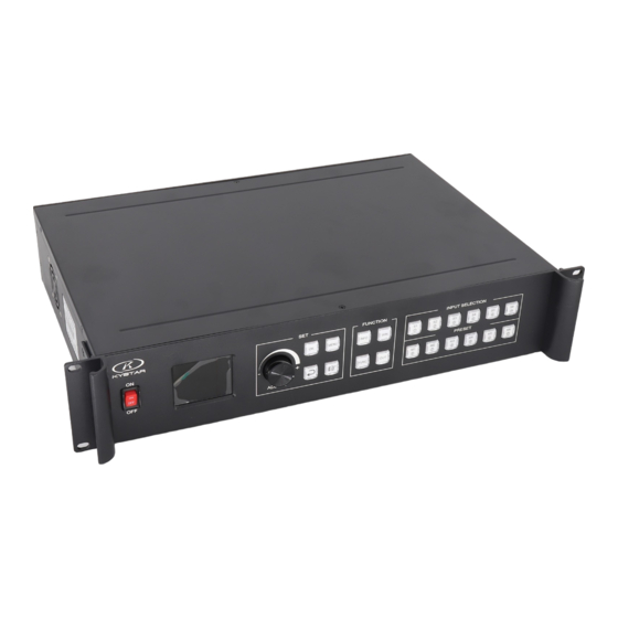
Multi-Image Splicing Processor 2. Hardware Introduction 2.1 Front Pane ① ② ③ ④ ⑤ ⑥ ⑦ ⑧ ⑨ ⑩ ⑪ ⑫ ⑬ POWER: AC 220V POWER switch; ON indicates that the power supply is ON, and OFF indicates that the power supply is OFF. LCD color screen: information display;... -
Page 7: Back Panel
Multi-Image Splicing Processor M1-M6: Shortcut mode call button; The shortcut mode button is displayed on the main menu interface, and the parameter input interface is displayed belowThe numbers 6-0 and the clear key. 2.2 Back Panel ① ② ③ ④ ⑤... -
Page 8: Device Debugging
Multi-Image Splicing Processor equipment through the upper computer software. 3. Device Debugging 3.1 Device Connection Device connection could be divided into three parts: power connection, signal connection and control connection (used for software debugging). Power connection: device power supply. Connection method: connect power cord to power plug. -
Page 9: Debugging Procedure
Multi-Image Splicing Processor 3.2 Debugging Procedure Step 1: Click “MENU” to enter into main menu interface and click “Device Mode” to select splicing mode: copy mode, horizontal mosaic, and vertical mosaic. Device Mode Copy Output Horizontal Mosaic Vertical Note: Mosaic All output displays are the same. - Page 10 Multi-Image Splicing Processor (2) Input by number of the front panel. For example, of the key refers to figure 1. Step 3: get back to main menu interface to select “Image layout” and enter into image number selecting interface to select image number required to be set. Image Layout Layout 1 Image 1...
- Page 11 Multi-Image Splicing Processor Clipped View Horizontal Image 1 Vertical Image 2 Image 3 Horizontal Vertical Size: ×1 ×100 ×10 Turn knob to select image Select by finger key Click “OK” to adjust Note: This step should be skipped if full display of signal source is required on large screen;...
-
Page 12: Case Explanation
Multi-Image Splicing Processor For Shortcut key call, only click of “M1-M6” in front panel is required, which is convenient when mode scenario is few. ⑥ ○ ⑦ ⑧ ⑨ ○ 0 For User mode call of Main Menu, click “MENU” and select “User Mode” to enter into its extraction interface. - Page 13 Multi-Image Splicing Processor Debugging Procedure: Step 1: click “MENU” and enter into main menu interface to select “Horizontal mosaic” of the first item “Device mode”. Device Mode Copy Output OUT1 OUT2 Horizontal Note: Mosaic All output interfaces are Vertical combined horizontally. Mosaic Note: as two transmitting cards are in the 1x2 arrangement, horizontal mosaics are needed then.
- Page 14 Multi-Image Splicing Processor connection of computer DVI interface with “S1-DVI” port of the back device, just click “S1” in the front which means choosing the signal to display on the screen. Step 4: After selecting signal and normal display of large screen, save all setting data.
- Page 15 Multi-Image Splicing Processor Display image 1 Display image 2 Debugging Procedure: Step 1: Click “MENU” to enter into main menu interface. Select “Device mode” and then “Vertical Mosaic”. Device Mode Copy Output OUT1 Horizontal Mosaic OUT2 Vertical Mosaic Note: All output interfaces Note: as two transmitting cards are in vertical arrangement, horizontal mosaics are needed then.
- Page 16 Multi-Image Splicing Processor Note: Input according to corresponding transmitting card size of each output interface. For OUT1, its horizontal size is 1792 and vertical size 704; for OUT2, they are 1792 and 640 respectively. Step 3: After inputting, select “Confirm” and return to main menu interface. The large screen splicing is finished, select signal source needed to display on screen and click corresponding key.
- Page 17 Multi-Image Splicing Processor Step 5: Click “MENU” and enter into main menu interface and select “Image layout” then Layout 3. Image Layout Layout 1 Layout 2 Image 1 Image 2 Image 3 Layout 3 Note: Default layout of the device is three equal parts. If it is desired, there is no need to carry out step 6.
- Page 18 Multi-Image Splicing Processor Note: The full screen size is 1792x1344 and image proportion is required as 1:2:1, so the sizes of the three images are respectively 448, 896 and 448. As the left images starts from the far left, its horizontal position is 0. The middle image follows the left image, so its horizontal position is 448.
-
Page 19: Function Key
Multi-Image Splicing Processor User Mode User Mode 1 Mode 1 Mode 2 Device Mode 2x2 Mode 3 Image Layout 1 Mode 4 Mode 5 Image 1 Mode 6 Mode 7 Mode 8 3.4 Function Key Using Menu LED-KS600 adopted a high brightness &contrast LCD screen to display the entire menu system, if the user does not have operation or operation timeout, the LED screen will show the default state.Operate the menu system by suing the knob and keys.The user can cheak and set its function and states convenient and intuitive to... - Page 20 Multi-Image Splicing Processor MENU area This areas contains a knob whicl can be pressed, a confirmation key(OK), a return key and a navigation key.The knob key the same as the confirmation key.when to press the return key, the menu system may be back to the previous menu in turn until to the default state immediately.
- Page 21 Multi-Image Splicing Processor WIN: Image key. Click this key to enter into its interface and signal source selection can be made in the following interface. Taking image 3 as instance, click “WIN” to enter into image switch interface which shows current signal sources of three images.
- Page 22 Multi-Image Splicing Processor functions. 1. Brightness adjustment The device supports 1-255 stairs brightness adjustment. Brightness of all screen body can be adjusted synchronously to meet customers’ different brightness adjustment requirements for different conditions. 2. Special effect switch The device supports switching of 16 kinds of special effects: fade in/out, seamless straight cut, vertical or horizontal comb, round cut-in or cut-out,diamond cut-in or cut-out and cross of every side.
- Page 23 Multi-Image Splicing Processor User can set priority of backup signals. When current signal fails, the system will detect automatically and call backup signal immediately; if signal returns to normal, the system will call original signal intelligently. Parallel system constructed by this function can guarantee reliability of scene. 9.
-
Page 24: Advanced Menu
Multi-Image Splicing Processor 3.5 Advanced Menu 1. Language Setting Set device language: English or Chinese 2. Output resolution Support single output resolution, user-defined resolution is available and support 30HZ, 50HZ and 60HZ frame rates. Default output resolution is 1920×1080@60HZ. 3. Factory Setting All data are cleared and the device returns to default state. -
Page 25: Technical Parameters
Multi-Image Splicing Processor 9. EDID Reset all EDID ports. 10. Mode Delete Delete wrongly saved or repeated mode(s). 11. Keyboard Lock Lock front panel key to avoid misoperation of irrelevant personnel. 4.Technical Parameters Input port Type Quantity specification CVBS(BNC) NTSC/PAL adaptive, supports 3D comb filter The VESA standard supports a maximum of 1920 x 1200@60Hz 1.3 Standard: supports a maximum of 1920 x 1200@60Hz HDMI... -
Page 26: Fqas
Multi-Image Splicing Processor 5. FQAs Q1: DVI, HDMI, VGA and CV Port Definition. A: DVI: DVI: Digital (HD) Video Signal, an interface standard jointly introduced by DDWG (Digital Display Working Group) combined by Silicon Image, Intel and etc. It has been optimized in speed, resolution, HDCP agreement and so on. Its signal source is normally desktop or laptop. - Page 27 Multi-Image Splicing Processor transmitting card. Q4: What is administrator password set in PC Software? A: No password. Just a click is ok. Q5: What are the reasons for failure of serial connection with the application of serial splicing processor? A: Possible reasons are as follows: ①...
-
Page 28: Appendix: Graphics Copy Mode And Extended Mode Setting
Multi-Image Splicing Processor Appendix: Graphics copy mode and extended mode setting 1. AMD Video Card Right-click on blank space of the desktop → Property →Setting → Advanced →enter into Graphics Drive Control Board →Right click → Copy/Extended mode. 2. NVIDIA Video Card Right-click on blank space of the desktop →...
Need help?
Do you have a question about the U3 and is the answer not in the manual?
Questions and answers