
Related Manuals for Kystar U3pro


Summary of Contents for Kystar U3pro
- Page 1 U3pro Multi-Image Splicing Processor User Manual Multi-Image Splicing Processor User Manual Beijing KYSTAR Technology Co.LTD...
- Page 2 U3pro Multi-Image Splicing Processor User Manual Statement Thank you for choosing our products. All rights of the manual are reserved by the company and no copy, delivery, distribution or storage of any form of the content is allowed without written permission from the company. The company reserves the right of modifications and improvements of any product function described in the document without prior notice.
- Page 3 U3pro Multi-Image Splicing Processor User Manual SAFETY PRECAUTIONS For your safety, please read this section carefully. Power Power supply of the device for normal operation is 100-200V AC. Please make sure that the product is operated within the voltage range.
-
Page 4: Table Of Contents
U3pro Multi-Image Splicing Processor User Manual Table of Contents 1. Product Introduction................1 2. Hardware Introduction................2 2.1 Front Panel..................2 2.2 Back Panel..................3 3. Device Debugging..................4 3.1 Device Connection.................4 3.2 Debugging Steps................4 3.3 Case Study..................8 3.4 Function Keys................16 3.5 Advanced Menu................19 4.Technical Parameters................20 5. -
Page 5: Product Introduction
1. Support various signal input includes conventional DVI, VGA, HDMI, CVBS, and SDI ; support 4K Ultra HD input and realize large screen point-to-point display. 2. Stand-alone can support user-defined layout of pixel 5.2 million (U3Pro) and support output pixels up to 15360 horizontally or 6144 vertically. -
Page 6: Hardware Introduction
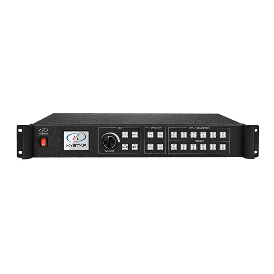
U3pro Multi-Image Splicing Processor 2. Hardware Introduction 2.1 Front Panel 1. POWER: Power switch of 220V AC, with ON indicating power connected and OFF indicating power disconnected. 2. LCD color screen: Information display screen showing device information and debugging information. -
Page 7: Back Panel
U3pro Multi-Image Splicing Processor 2.2 Back panel 1. MONTOR: Pre-monitor channel for monitoring input signal source or output interface information. 2. OUTPUT: Programmatic output channel for pure digital DVI-D output and transmitting card connection. 3. LANI: 100MB network control port which can realize device debugging by software with its connection with computer 100MB network interface. -
Page 8: Device Debugging
U3pro Multi-Image Splicing Processor 3. Device Debugging 3.1 Device Connection Device connection could be divided into three parts: power connection, signal connection and control connection (used for software debugging). Power connection: device power supply. Connection method: connect power cord to power plug. -
Page 9: Debugging Steps
U3pro Multi-Image Splicing Processor 3.2 Debugging Steps Step 1: Click “MENU” to enter into main menu interface and click “Device Mode” to select splicing mode: copy mode, horizontal mosaic, vertical mosaic and cross mosaic. Device Mode Copy Output Horizontal Splicing... - Page 10 U3pro Multi-Image Splicing Processor Step 3: get back to main menu interface to select “Image layout” and enter into image number selecting interface to select image number required to be set. Image Layout Layout 1 Image 1 Layout 2 Layout 3...
- Page 11 U3pro Multi-Image Splicing Processor Note: This step should be skipped if full display of signal source is required on large screen; while if certain signal source of multi-image is needed to be extracted, only setting of signal source image is required; if horizontal size or vertical size is 0, it means no local extraction is required in this direction.
-
Page 12: Case Study
U3pro Multi-Image Splicing Processor 3.3 Case Study Device debugging steps are explained by following cases. Case 1: screen size is 2688× 1664 and loading transmitting card is shown as picture below: Requirement: whole computer desktop should be displayed completely. 1440... - Page 13 U3pro Multi-Image Splicing Processor Step 2: Click “OK” to return to main menu interface; select “Large screen parameters” to set size of each output interface. Screen Parameters OUT1 Horizontal Size: 1920 OUT2 Vertical size: 1080 OUT3 Confirm Cancel OUT4 ×100 ×10...
- Page 14 U3pro Multi-Image Splicing Processor Note: Mode 1 is default startup data of device boot; it’s suggested that the most common mode should be saved to Mode 1 and the device can save 32 kinds of modes at most. Case 2: Screen size is 6880× 576 and loading transmitting card is shown as picture below: Requirement: 1) Whole computer desktop should be displayed completely..
- Page 15 U3pro Multi-Image Splicing Processor Step 2: Click “OK” to return to main menu interface; select “Large screen parameters” to set size of each output. Screen Parameters OUT1 Horizontal size:1920 OUT2 Vertical Size:1080 OUT3 Confirm Cancel OUT4 ×100 ×1 ×10 Rotate knob to select output Select by Finger key Click “OK”...
- Page 16 U3pro Multi-Image Splicing Processor Note: Mode 1 is default startup data of device boot; it’s suggested that the most common mode should be saved to Mode 1 and the device can save 32 kinds of mode at most. For above operation which has fulfilled the first requirement of the program, namely splicing of the whole screen, image is displayed completely and correct data are saved.
- Page 17 U3pro Multi-Image Splicing Processor Step 7: According to operation above, screen body has been divided into three images with proportion of 1:2:1. Default display content of each image is S1. If different signal sources should be designated for each image, click of front panel to enter into image switch interface.
-
Page 18: Function Keys
U3pro Multi-Image Splicing Processor 3.4 Function key: Brief explanation of function key: INFO: Information query key. Click this key and enter into its interface showing whether all signal sources are inputting normally. Its interface is shown as below. Red light means signal is lost while green one shows signal is normal. - Page 19 U3pro Multi-Image Splicing Processor Output condition control 黑屏 蓝屏 Note: Display blank screen 正常 FUNC: Function key. Click this key to enter into its interface which includes: brightness adjustment, special effect switch, VGA adjustment, image matting setting, edge feather, transparency setting, intelligent warm backup, preview monitor, IP setting, serial port, freeze frame, local and global, color space, input brightness and switch time.
- Page 20 U3pro Multi-Image Splicing Processor 6. Edge feather By image edge blanking, it makes transition more smooth and soft, and make image overlay more harmonious and vivid. 7. Transparency setting he product can adjust image transparency and even point-by-point adjustment to make application scene more colorful.
- Page 21 U3pro Multi-Image Splicing Processor Pre-monitoring input and output: can monitor large screen display, namely output. Preview output channel: monitor all input and output. Preview input channel: monitor signal source.
-
Page 22: Advanced Menu
U3pro Multi-Image Splicing Processor 3.5 Advanced Menu Language setting Set device language: English or Chinese Output resolution Support single output resolution, user-defined resolution is available and support 30HZ, 50HZ and 60HZ frame rate. Device default output resolution is 1920× 1080@60HZ. -
Page 23: Technical Parameters
Support point-to-point mosaics, multi-machine can realize greater resolution of mosaic output with cascade. · Render 3 (U3pro) / 4(U4 ) / 6(U6) or fewer images on screen at the same time, these images can be Multiple-image Output from the same or different input signals. -
Page 24: Q&A
U3pro Multi-Image Splicing Processor 5. Q&A Q1: DVI, HDMI, VGA and CV Port Definition. A: DVI: Digital (HD) Video Signal, an interface standard jointly introduced by DDWG (Digital Display Working Group) combined by Silicon Image, Intel and etc. It has been optimized in speed, resolution, HDCP agreement and so on. Its signal source is often desktop and laptop. - Page 25 U3pro Multi-Image Splicing Processor A: Possible reasons are as follows: 1. Wrong selection of COM port. Just click “Confirm” and re-click “opening serial port” key. 2. Occupation of serial port. Two or more software windows are not allowed to be open simultaneously.
-
Page 26: Appendix:graphics Copy Mode And Extended Mode Setting
U3pro Multi-Image Splicing Processor Appendix: Graphics copy mode and extended mode setting 1. AMD Video Card Right-click on blank space of the desktop → Property →Setting → Advanced →enter into Graphics Drive Control Board →Right click → Copy/Extended mode. -
Page 27: Nvidia Video Card
U3pro Multi-Image Splicing Processor 2. NVIDIA Video Card Right-click on blank space of the desktop → Property → Setting → Advanced →enter into Graphics Drive Control Board →Right click →Copy/Extended mode.
Need help?
Do you have a question about the U3pro and is the answer not in the manual?
Questions and answers