Advertisement
Installation Sheet
June 2006
Introduction
This manual provides instructions for the installation,
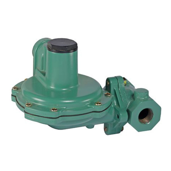
Startup, and adjustment of the Type HSR pressure
regulator. If maintenance is required, refer to the Type
HSR Instruction Manual, form 5753. To receive a copy of
the instruction manual, contact your Fisher Sales Office or
Sales Representative.
Specifications
Maximum Emergency Inlet Pressures
150 psi (10,3 bar)
Maximum Emergency Outlet (Casing) Pressures
25 psig (1,72 bar)
Outlet Pressure Ranges
4 to 6-inches w.c. (10 to 15 mbar),
6 to 8-inches w.c. (15 to 20 mbar),
8 to 10-inches w.c. (20 to 25 mbar),
10 to 12.5-inches w.c. (25 to 31 mbar),
12.5 to 20-inches w.c. (31 to 50 mbar),
20 to 35-inches w.c. (50 to 87 mbar),
1.25 to 2.2 psig (0,09 to 0,15 bar)
Temperature Capabilities
-20° to 160°F (-29° to 71°C)
Installation
WaRnIng
!
Personal injury, equipment damage, or
leakage due to escaping gas or bursting
of pressure-containing parts might result
if these regulators are overpressured or
installed where service conditions could
exceed the limits for which the regulators
were designed, or where conditions exceed
any ratings of the adjacent piping or
piping connections. To avoid such injury
or damage, provide pressure-relieving
or pressure-limiting devices (as required
by the appropriate code, regulation or
standard) to prevent service conditions
from exceeding those limits.
additionally, physical damage to a
regulator could cause personal injury and
property damage due to escaping gas. To
avoid such injury and damage, install the
regulator in a safe location.
a regulator may vent some gas to the
atmosphere in hazardous or flammable gas
service, vented gas might accumulate and
cause personal injury, death or property
damage due to fire or explosion. Vent
a regulator in hazardous gas service to
a remote, safe location away from air
(1)
(1)
(2)
www.emersonprocess.com/regulators
intakes or any hazardous location. The
vent line must be protected against
condensation or clogging.
Before installing the regulator, check for damage which
might have occurred in shipment. Also check for dirt
or foreign matter which may have accumulated in the
regulator body or in the pipeline. Apply pipe compound to
the male threads of the pipeline and install the regulator
so that the flow is in the direction of the arrow cast on
the side of the body. The diaphragm actuator assembly
can be rotated to any position relative to the body, in 90°
increments. Remove the two cap screws that hold the
body to the actuator in order to rotate the diaphragm
actuator assembly.
Do not install the regulator in a location where there can
be excessive water accumulation, such as directly beneath
a downspout or in an undrained pit.
To obtain the maximum flow capacities or other
performance characteristics, the length of pipe from the
regulator outlet to the meter should have no bends and
should be the same size as the regulator outlet. Replace
the regulator if water gets into the spring case or the lower
casing of the regulator.
CauTIOn
You are advised to use new vent piping
because defective threads on the relief
vent piping may interfere with the venting
assembly if the piping obstructs the
movement of the vent flapper.
On indoor installations, the vent should be piped outside
the building. Remove the screen from the regulator vent
connection and connect vent piping from that connection
to the outdoors. Install a weather and insect resistant
vent assembly on the outside end of the pipe. Inspect
the vent opening regularly. On some installations, it may
be necessary to install the regulator beneath a protective
hood. The vent should be pointing or sloping down
sufficiently to allow any condensate to drain. Also check
the regulator periodically for external or internal corrosion.
Overpressure Protection
WaRnIng
!
Some type of overpressure protection is
needed if actual inlet pressure can exceed
the outlet pressure rating. Overpressuring
any portion of this equipment may cause
damage to regulator parts, leaks in
the regulator, or personal injury due to
bursting of pressure-containing parts or
explosion of accumulated gas.
Type HSR
Advertisement
Table of Contents

Related Manuals for Emerson Fisher HSR


Summary of Contents for Emerson Fisher HSR
- Page 1 Type HSR Installation Sheet June 2006 Introduction This manual provides instructions for the installation, intakes or any hazardous location. The startup, and adjustment of the Type HSR pressure vent line must be protected against condensation or clogging. regulator. If maintenance is required, refer to the Type HSR Instruction Manual, form 5753.
- Page 2 For further information visit www.emersonprocess.com/regulators The Emerson logo is a trademark and service mark of Emerson Electric Co. All other marks are the property of their prospective owners. Fisher is a mark owned by Fisher Controls, Inc., a business of Emerson Process Management.
Need help?
Do you have a question about the Fisher HSR and is the answer not in the manual?
Questions and answers