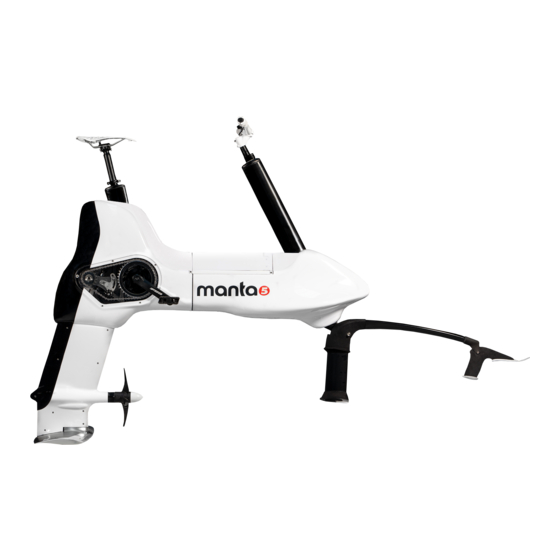
Manta 5 XE-1 Tutorial
How to replace the propeller drive shaft
Hide thumbs
Also See for XE-1:
- Owner's manual (24 pages) ,
- Initial assembly manual (16 pages) ,
- Tutorial (9 pages)
Advertisement
Quick Links
This tutorial shows how to replace the propeller drive shaft
Before you start: For this work instruction it is assumed that the XE-1 is upright and supported by the foils.
In a configuration where the bike is supported in a workshop or inverted on the handlebars and seat, the
Rear Foil can be removed and the task can be performed without having to remove the Chain Guard and RH
Rear Buoyancy.
1. REMOVE CHAIN GUARD (only required if Rear Foil is fitted)
TOOLS REQUIRED
ID
Description
N/A
2.5 mm Hex Drive / Allen Key
1.1 Remove the five 8-Gauge Machine Screws that is used to attach the Chain Guard to the RH Rear
Buoyancy. [Tools: 2.5 mm Hex Drive]
1.2 Remove the transparent acrylic Chain Guard over the RH Crank and Pedal.
Task
Loosen 8 Gauge Machine Screws
Advertisement

Related Manuals for Manta 5 XE-1


Summary of Contents for Manta 5 XE-1
- Page 1 This tutorial shows how to replace the propeller drive shaft Before you start: For this work instruction it is assumed that the XE-1 is upright and supported by the foils. In a configuration where the bike is supported in a workshop or inverted on the handlebars and seat, the Rear Foil can be removed and the task can be performed without having to remove the Chain Guard and RH Rear Buoyancy.
-
Page 2: Tools Required
INFORMATION: Do not use solvents to clean the Chain Guard. Use warm soapy water (dishwashing liquid soap) instead. 2. Remove Rear RH Buoyancy (only required if Rear Foil is fitted) TOOLS REQUIRED Description Task Long Nose Pliers Remove Buoyancy Clips 2.1 Remove all seven Buoyancy Clips. - Page 3 INFORMATION: It is good practice to remove the white short Buoyancy Clip in front of the Seat Tube last. The two long clips go at the back. 2.2 With the crank approximately in the 6 O’clock position, remove the Rear RH Buoyancy module over the Crank and Pedal.
- Page 4 REMOVAL OF THE STRUT COWL IS REQUIRED TO GAIN ACCESS TO THE PROPELLER DRIVE SHAFT 3. Removing the Strut Cowl TOOLS REQUIRED Description Task M3 Hex Key Loosen M4 Cap Screws 3.1 Remove the seven M4 cap screws from the RH side of the Strut Cowl [Tools: M3 Hex]. INFORMATION : The seven M4 Nylock Nuts positioned in the hex shaped pockets on the LH Strut Cowl can fall out.
- Page 5 CAUTION: Do not use pliers to remove the Strut Cowl Collar as it may cause damage to the component. The Collar is easily rotated by hand and can be removed with little force. 3.3 With the screws and Strut Cowl Collar Removed, the two Strut Cowl halves (LH & RH) is held to each other only by being clipped together at the bottom trailing edge of the Strut Cowl.
- Page 6 3.4 Remove the RH Strut Cowl and support the LH Strut Cowl as it is only held from falling by the Cooling Hose being routed through behind the Lower LH Motor Mount Bracket. Keep LH Strut Cowl in place. INFORMATION : Removal of the Strut Cowl provides access to the Top and Bottom Gearbox, Vertical Drive Shaft, Bayonet (Frame to Foil attachment) and Propeller Drive Shaft Assembly.
- Page 7 Description Task 40 mm Open Wrench Loosen Propeller Drive Shaft Hub 4.1 To remove the Propeller Drive Shaft Assembly, loosen the Propeller Hub by rotating it clockwise. Pull the Propeller Drive Shaft forward to disengage it from the Gearbox Output Shaft. [Tools: 40 mm Open Wrench] 4.2 TO REPLACE THE PROPELLER DRIVE SHAFT, SIMPLY PULL IT OUT FROM THE HUB ASSEMBLY AND INSERT THE REPLACEMENT SHAFT INTO THE HUB ASSEMBLY...
- Page 8 5. Fit Propeller Drive Shaft Assembly TOOLS REQUIRED Description Task 40 mm Open Wrench Fasten Propeller Drive Shaft Hub...
- Page 9 5.1 Apply Tef-Gel (or equivalent) to the internal spline of the Propeller Drive Shaft. Align the Propeller Drive Shaft with Gearbox Output Shaft Spline and push the Propeller Drive Shaft onto the Gearbox Input Shaft. [Tools: By Hand Only] INFORMATION: The LH (left hand) thread of the Propeller Hub ensures that it is self-tightening while the Propeller is driven.
- Page 10 INFORMATION: The LH thread of the Propeller Hub ensures that it is self-tightening while the Propeller is driven. With the fine thread extra caution must be taken not to cross thread with that of the Frame. To find the beginning of the thread, slowly rotate the Hub clockwise until you can feel it step off the first thread.
- Page 11 62 With the two internal molded locking boss features of the Prop Collar facing the Strut Cowl and aligned in the 11 & 5 o’clock position, push the Prop Collar into place while holding the two Strut Cowl halves together. 6.3 Rotate the Prop Collar clockwise (by hand only) through approximately 70 degrees until the lock stop is reached.
- Page 12 6.4 With the M4 Nylock Nuts held in the nut pockets of the LH Strut Cowl, fix the two Strut Cowl halves in place by fitting and fastening the seven M4X20 stainless steel cap screws to a torque value of 2.5 to 3 Nm. [Tools: M3 Hex Drive].
- Page 13 7.1 With the Crank approximately in the 6 O’clock position, position the Rear RH Buoyancy Module by sliding it over the top of the RH Pedal and Crank. INFORMATION: If the RH Cranks are fitted, the Chain Guard must be removed before fitting the Rear RH Buoyancy to the bike.
- Page 14 7.3 Fit all seven Buoyancy Clips to secure both LH and RH Buoyancy halves to the hydrofoiler. [Tools: Long Nose Pliers]. 8. Fit Chain Guard TOOLS REQUIRED...
- Page 15 Description Task 2.5 mm Hex Drive / Allen Key Loosen 8 Gauge Machine Screws 8.1 Fit the transparent acrylic Chain Guard over the RH Pedal and Crank and onto the RH Rear Buoyancy. 8.2 Align the Chain Guard with the recess on the RH Rear Buoyancy with screw holes aligned. Fit five 8- Gauge Machine Screws and fasten lightly.
- Page 16 INFORMATION: If the machine screws are over tightened, they will slip in the insert without causing serious damage. To maximize the life of the Buoyancy Inserts, avoid over tightening and subsequent wear of the inserts.
Need help?
Do you have a question about the XE-1 and is the answer not in the manual?
Questions and answers