Manta 5 XE-1 Tutorial
Replace the bayonet upright
Hide thumbs
Also See for XE-1:
- Owner's manual (24 pages) ,
- Initial assembly manual (16 pages) ,
- Tutorial (16 pages)
Advertisement
Quick Links
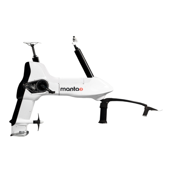
This tutorial shows how to replace the Bayonet Upright
Before you start: For this work instruction it is assumed that the XE-1 is upright and supported in a
workshop stand. This task can also be performed with the XE-1 inverted and supported on its handlebars
and seat. For Safety reasons, make sure that the Propeller and Battery is removed. Also remove the Rear
Foil and Front Tiller assembly. The Rear Buoyancy set is not shown in the images of this instruction but
there is no need to remove it for this task.
1. Removing the Strut Cowl
TOOLS REQUIRED
ID
Description
N/A
M3 Hex Key
3.1 Remove the seven M4 cap screws from the RH side of the Strut Cowl [Tools: M3 Hex].
INFORMATION : The seven M4 Nylock Nuts positioned in the hex shaped pockets on the LH
Strut Cowl can fall out. Secure the nuts or remove and store them safely.
3.2 Unlock the Strut Collar by rotating anti-clockwise through 70 degrees. Remove the Collar by sliding it
forward over the Propeller Drive Shaft.
Task
Loosen M4 Cap Screws
Advertisement

Related Manuals for Manta 5 XE-1


Summary of Contents for Manta 5 XE-1
- Page 1 This tutorial shows how to replace the Bayonet Upright Before you start: For this work instruction it is assumed that the XE-1 is upright and supported in a workshop stand. This task can also be performed with the XE-1 inverted and supported on its handlebars and seat.
- Page 2 CAUTION: Do not use pliers to remove the Strut Cowl Collar as it may cause damage to the component. The Collar is easily rotated by hand and can be removed with little force. 3.3 With the screws and Strut Cowl Collar Removed, the two Strut Cowl halves (LH & RH) is held to each other only by being clipped together at the bottom trailing edge of the Strut Cowl.
-
Page 3: Tools Required
3.4 Remove the RH Strut Cowl and support the LH Strut Cowl as it is only held from falling by the Cooling Hose being routed through behind the Lower LH Motor Mount Bracket. Keep LH Strut Cowl in place. INFORMATION : Removal of the Strut Cowl provides access to the Top and Bottom Gearbox, Vertical Drive Shaft, Bayonet (Frame to Foil attachment) and Propeller Drive Shaft Assembly. - Page 4 Description Task 5 mm Hex Key Remove M6 ALU Screws 10 mm Open Wrench Remove M6 Nylock Nuts 2.1 Remove all three M6 nylock nuts on the left hand side of the Bayonet Upright. [Tools: 5 mm Hex Key, 10 mm Open Wrench] 2.2 Remove all three aluminum M6 Machine Screws (45 mm length) [Tools: By hand only]...
- Page 5 2.3 Remove the Bayonet Upright (heat treated aluminum extrusion) from the XE-1 Frame by sliding it forward. [Tools: By hand only] INFORMATION : On a small number on XE-1 Frames it was found that the aluminum welding bead in front of the Bayonet Upright was built up too high and this causes an obstruction that prevents the Bayonet Upright from being removed.
- Page 6 3. Fit Bayonet Upright TOOLS REQUIRED Description Task 5 mm Hex Key Remove M6 ALU Screws 10 mm Open Wrench Remove M6 Nylock Nuts 3.1 Fit replacement Bayonet Upright by sliding it onto the Frame from the front. Ensure that the narrow end of the taper is at the front.
- Page 7 4. Fit Strut Cowl TOOLS REQUIRED Description Task Hex Key 3 mm M4 Cap Screws 4.1 Position the RH Strut Cowl to align with the LH Strut Cowl. Gently push the bottom of the trailing edges of the two cowl halves together until you hear a clicking sound as the trailing edges interlock.
- Page 8 4.2 With the two internal molded locking boss features of the Prop Collar facing the Strut Cowl and aligned in the 11 & 5 o’clock position, push the Prop Collar into place while holding the two Strut Cowl halves together. 4.3 Rotate the Prop Collar clockwise (by hand only) through approximately 70 degrees until the lock stop is reached.
- Page 9 4.4 With the M4 Nylock Nuts held in the nut pockets of the LH Strut Cowl, fix the two Strut Cowl halves in place by fitting and fastening the seven M4X20 stainless steel cap screws to a torque value of 2.5 to 3 Nm. [Tools: M3 Hex Drive].
Need help?
Do you have a question about the XE-1 and is the answer not in the manual?
Questions and answers