Table of Contents
Advertisement
Quick Links
Advertisement
Table of Contents

Subscribe to Our Youtube Channel
Related Manuals for djm direct DJMBAS80


Summary of Contents for djm direct DJMBAS80
- Page 1 Item No.:DJMBAS80 Band Saw Band Saw Original Operating Manual...
-
Page 2: Dear Customer
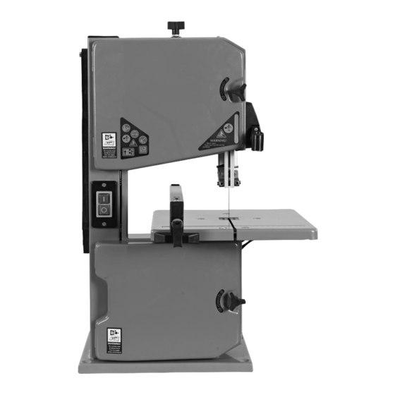
1.Introduction 2.Device Description MANUFACTURER: 1. Setting Knob for Blade Tension DJM Direct.com 2. Upper Housing Door 3. ON/OFF Switch Unit 43 Churchill Way, 4. Rip Fence Lomeshaye Industrial Estate, 5. Lower Housing Door Nelson, Lancashire BB9 6RT UK 6. Door Lock DEAR CUSTOMER 7. - Page 4 3. Unpacking Protect eyes, face, and head from objects that may be thrown from the unit. Always wear safety goggles or ●Open the packaging and remove the device carefully. safety glasses with side shields when operating. ●Remove the packaging material as well as the Wear appropriate hearing protection.
-
Page 5: Specific Safety Rules
Do not use the cable for purposes for which it is not ● Tilting of the workpiece due to inadequate intended. Do not use the cable to pull the plug out of support. the outlet. Protect the cable from heat, oil and sharp ●... -
Page 6: Technical Data
6. Contents Supplied • Impossibility of stopping the machine in the best possible conditions The band saw comes partially assembled and is • Variations in the rotational speed of tools shipped in carefully packed carton. After all the • Failure of the power supply parts have been removed from the carton, you •... -
Page 7: Application Conditions
7. Introduction 9. Machine Use and Care -Do not use low-output electric tools for heavy work. Your new band saw will more than satisfy your Do not use the electric tool for purposes for which it expectations. It has been manufactured under is not intended. - Page 8 10. Assembly This band saw was partially assembled at the factory. To assemble your machine follow the below instructions. × × Work Table 1. Remove the two screws, two knurled nuts and U shape block from the work table. 2. Guide work table over the blade and place it on VIEW the table trunnion.
- Page 9 11. Set Up Adjusting the Blade Tension This tracking adjustment is required to have the blade run dead center on the rubber tyres of the band saw wheels: ● Turning the setting knob clockwise increases Locker the blade tension. ● Turning the setting knob counter- clockwise reduces the blade tension.
- Page 10 2. Loosen locking screws. 3. Using a try square, set the table at right angles to the blade and tighten the locking screws again. 4. Loosen locking nut and adjust limit stop screw until it touches the working table. Max: 45° Work Table Limit Stop Screw Locking Nut...
-
Page 11: Operation
Adjusting the Blade Guard Mounting the saw in the stable and flat supporting surface The blade guard protects against unintentional contact with the saw blade and from chips flying 1. Drill 4 holes in the supporting surface. about. In order for the upper blade guard to 2. -
Page 12: Maintenance
13. Maintenance ON/OFF Switch for Lamp Press "I" to turn on the lamp. Warning! Prior to any adjustment, Press "O" to turn off the lamp maintenance or service work This light switch can only work when the ON/OFF disconnect the mains power plug! switch for the product is turned on. - Page 14 Adjusting the Blade Tension This tracking adjustment is required to have the blade run dead center on the rubber tyres of the band saw wheels: ● Turning the setting knob clockwise increases the blade tension. ● Turning the setting knob counter - clockwise reduces the blade tension.
- Page 15 Thrust bearing adjustment 1. Loosen the two screws and remove the under blocks. 2. Loosen the three screws and Remove the working table from the table trunnion . 4. Tighten the thrust bearing locking screw. 3. Loosen the two knobs and remove the bench Guide pin adjustment angle gauge.
- Page 16 14. Transport 9. Tighten the thrust bearing locking screw. Guide pin adjustment 1. Turn off the power tool before any transport 1. Loosen screws. and disconnect it from the power supply. 2. Press guide pins together, keep 0.5 mm 2. Apply the power tool at least with two people, distance between guide pin and the saw blade.
-
Page 17: Troubleshooting
Trouble Shooting Problem Cause Remedy 1. Arrange for inspection of the 1. Motor, cable or plug defective, machine by a specialist. Never repair Motor does not fuses burnt the motor yourself. Danger! Check work 2. Housing cover open (limit switch) fuses and replace as necessary 2. - Page 19 Description Description Lower Housing Door Big Flat Washer 6 Door Locker M6×26 Key 5×14 Lock Nut M6 Band Saw Wheel-Lower Screw M5×25 Column Plug Nut M5 Setting Knob for Blade Tension Flat Washer 4 Thin Nut M8 Screw M4×8 Adjusting Rod Upper Housing Door Support Bushing Push Stick...
- Page 20 Description Description Flat Washer 8 Upper Blade Guide Table Insert Upper Guide Pin Work Table Bearing Shaft Bolt M6×20 Bearing 625-2Z U-Shaped Blocker Screw M6×12 Knurled Nut Pin 2.5×12 Rip Fence Locker Lower Blade Guide Pin 3×16 Lower Guide Pin Connecting Bushing Upper Microswitch Cable Flat Washer 10...
- Page 21 ONLY FOR DJMBAS80 Description Screw M4×10 Lock Washer 4 Screw M4×25 Nut M4 Cable Clip Hood Circuit Board Housing Screw ST4.2x13 Lamp Circuit Board Screw ST2.9x6.5 Lamp Cable 1 SM2.54-2P Connector Male End SM2.54-2P Connector Female End Lamp Cover Lamp...
- Page 22 Band Saw - Part. No. DJMBAS80 2006/42/EC Machinery Directive 2014/30/EU EMC Directive EN ISO 12100:2010 EN 55014-1:2017 EN 55014-2:2015 EN 61000-3-2:2014 EN 61000-3-3:2013 Date:05/17/2021...
Need help?
Do you have a question about the DJMBAS80 and is the answer not in the manual?
Questions and answers