Table of Contents
Advertisement
Quick Links
INDUSTRIAL BATTERY GROUP
Doc Ref:
User's Manual
ED2015-0544
Lithium-ion Battery System (504V / 45 Ah)
Lithium-ion Stationary Battery System
P/N 777308-00
BTR-0504V-VL45E-NCA-009M
504V / 45Ah
Type of document:
User Manual
Created on: 04/12/2015
This document is
Saft
property. Any reproduction, diffusion or communication, even partial, are liable to prosecution without formal authorization.
Advertisement
Table of Contents

Subscribe to Our Youtube Channel
Related Manuals for Saft 777308-00


Summary of Contents for Saft 777308-00
- Page 1 INDUSTRIAL BATTERY GROUP Doc Ref: User’s Manual ED2015-0544 Lithium-ion Battery System (504V / 45 Ah) Lithium-ion Stationary Battery System P/N 777308-00 BTR-0504V-VL45E-NCA-009M 504V / 45Ah Type of document: User Manual Created on: 04/12/2015 This document is Saft property. Any reproduction, diffusion or communication, even partial, are liable to prosecution without formal authorization.
- Page 2 DOCUMENT REVISION Version Date Changes First issue 9 Synerion modules version based on the ED2014- 04/12/2015 0210_UM_10 Syn48E battery_rev2 2/45...
- Page 3 In case any of the instructions contained in the user and the maintenance manuals are not applied, Saft’s warranty on the battery is no longer applicable and Saft disclaim any liability for any and all direct, indirect or consequential damages or losses resulting thereof.
- Page 4 (7) The battery systems must be used with the Synerion 48E modules described in paragraph 2. Saft does not assure the behavior and the safety of the battery system if another module is used. (8) In case of contactor stuck closed (Alarm 18 rising), stop immediately the battery charge or discharge.
-
Page 5: Table Of Contents
TABLE OF CONTENTS INTRODUCTION ........................7 1.1. Applicability ........................7 1.2. Acronyms ........................7 1.3. Symbols .......................... 8 1.4. Referenced documents ....................8 UNPACKING AND INSPECTION..................9 2.1. Battery characteristics ....................11 GENERAL DESCRIPTION OF THE BATTERY SYSTEM ..........13 3.1. - Page 6 6.2.2. Battery state of charge checking ................33 6.2.3. Battery recharge in storage ..................33 MAINTENANCE ......................... 34 PACKAGING AND TRANSPORT ..................35 8.1. Battery classification ..................... 35 8.2. Training ......................... 35 8.3. Battery packing ......................35 8.4. Charging state for transportation................... 35 8.5.
-
Page 7: Introduction
1. INTRODUCTION This document contains the operating rules of the SAFT Lithium-Ion battery unit model for Stationary Batteries 9 modules 504V max with limitation at 486V P/N 777308-00. 1.1. Applicability This document describes functionalities and behaviour implemented in the BMM software version 0.65 revH. -
Page 8: Symbols
1.4. Referenced documents A reference document is used as a basis of work. Its strict application cannot be required. : Document title Emitter Reference CAN OPEN dictionary for BMS SAFT SDU/SEL/DH 09-0974 [RD1] Diagnostic WinBMS Software User User_Manual_WinBM [RD2]... -
Page 9: Unpacking And Inspection
Check the packing material for any damages before accepting delivery from the carrier. If there is any sign of damage, report it to the carrier and to SAFT and make a “certified letter with acknowledgement” to the transporter. For each battery system, ensure that the following parts are delivered: ... -
Page 10: Figure 3: Power Cable Connection For 9 Modules Battery
(see drawing on Appendix VI) Figure 4: Communication ribbon cables 1 CDROM or USB key with SAFT diagnostic software (DiagWinBMS) and its User Manual It is advised to save the original packaging for reuse in case of later shipment. -
Page 11: Battery Characteristics
2.1. Battery characteristics The table below gives the main characteristics of the battery and BMM: 9 modules Unit Battery electrical characteristics Nominal voltage Maximum voltage Minimum voltage Minimum capacity (C/3, 25°C) 31.5 Maximum continuous charge current allowed (normal charge) @ +35°C @ +20°C @ 0°C @ -20°C... - Page 12 60°C) Storage battery temperature -20 to +75 °C range Recommended storage battery temperature range (to preserve < +40 °C lifetime) Recommended storage BMM temperature range (to preserve -20 to +65 °C lifetime) Maximum altitude 2000 Interior without air conditioning, not condensing: Environmental conditions B type following EN50178-1:1997 - Environment temperature...
-
Page 13: General Description Of The Battery System
3. GENERAL DESCRIPTION OF THE BATTERY SYSTEM 3.1. Synoptic CAN Open RS485 Customer Diagnostic Power supply: 24V -BATT +BATT Module supply : 5V Module: 14 cells in series (54V max) Module: 14 cells in series (54V max) Module: 14 cells in series (54V max) Module: 14 cells in 9 modules in series... -
Page 14: Battery System
3.2. Battery system Li-ion battery is made of: An assembly of Li-ion modules connected in series. A Battery Management Module (BMM) which is the interface between battery and customer application. An external power supply (24V) is needed to supply the BMM (see §2.1 for characteristics). 3.2.1. -
Page 15: Hmi
3.3. HMI The figure below shows the BMM interface: Battery converter Battery connection 24Vdc Power connection RS485 (+polarity) supply (+polarity) Diagnostic Battery converter Battery connection Communication connection CAN Communication (-polarity) to EMS (-polarity) to SMU Connection from modules Connection to converter ... -
Page 16: Assembly Installation
Installation The cabinet in which the battery will be installed must be in closed electrical enclosure according to chapter 5.2.7 of EN50178-1:1999 standard. If the product is brought to the installation location from a cold environment, condensation may form and this may lead to damage the electronic equipment. Before commissioning, the product must be dry. -
Page 17: Electrical Interfaces
3.8. Electrical interfaces 3.8.1. Power connection Power connectors used for Battery and Inverter (-polarity) connections: PV-ADBP4/6 from Multi- contact. Figure 7: -polarity power connector Power connectors used for Battery and Inverter (+polarity) connections: PV-ADSP4/6 from Multi-contact. Figure 8: +polarity power connector 3.8.2. -
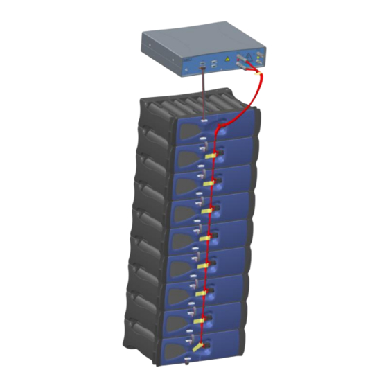
Page 18: Figure 9: Battery Connection
Note: the following picture represents the battery connection (only 5 on 9 modules are represented). Module to BMM communication connection Module to BMM power connection Inter-module power connection Inter-module communication connection CAN termination connector on the last module Figure 9: Battery connection Don’t short-circuit the module terminals. -
Page 19: Communication Connector
These connectors are insulated from High voltage by a protective separation. 1 : Spare_1 2 : CAN_L 3 : GND (0V) 4 : Saft reserved (don’t connect) 5 : Spare_2 6 : Saft reserved (don’t connect) 7 : CAN_H 8 : Saft reserved (don’t connect) 9 : Saft reserved (don’t connect) -
Page 20: Diagnostic Interface
1 : RS-485_A (+) 2 : RS-485_B (-) 3 : CAN_L 4 : CAN_H 5 : GND (0V) 6 : 24Vdc (Power Supply) 7 : N/U 8 : CAN_L_SMU (Saft only) 9 : CAN_H_SMU (Saft only) Figure 12: Diagnostic connector 20/45... -
Page 21: Battery Management And Operating Instructions
4. BATTERY MANAGEMENT AND OPERATING INSTRUCTIONS 4.1. General principle Charge and discharge of the Li-ion battery must be monitored and managed with respect to physical parameters such as cell voltages, battery current and module temperature. This management is performed by the BMU board inside the BMM, which runs algorithms and monitors the battery. -
Page 22: Over-Discharge Protection
4.2.2. Over-discharge protection Two kinds of protection are used to prevent over discharge: regarding cells voltage, BMM could open the contactor. The two kinds of protection are: Cell under voltage first level: one cell voltage < 2.5V Cell under voltage second level (redundant): one cell voltage < 2V 4.2.3. -
Page 23: Communication
4.3. Communication CAN Open communication bus: Baud rate: 250kBd Standard CAN (11 bits identifier) 120Ω resistor terminal not connected inside the BMM For objects dictionary, see document [RD2]. Nota: as the 120Ω resistor terminal is not connected inside the BMM, it is the responsibility of user to integrate it in the CAN bus. -
Page 24: Operational States
4.5. Operational states NOMINAL SLEEP SAFE INIT STAND BY Figure 13: Battery modes Off: in this mode, BMU is not supplied. Thus, the battery is not supervised by the BMM. Init: in this mode, the battery is unavailable, meaning it is disconnected from the overall system. The BMU proceeds to its internal tests: ... -
Page 25: Precharge
Sleep: this state places the electronic devices inside modules (SMU) and BMM in low power consumption: the contactor is open and there is no possibility to charge and discharge battery. However, CAN communication is still available with BMM. Safe: two kinds of faults can occur: warnings and alarms. At warning level, the battery system stays in nominal mode and only informs about the fault code. -
Page 26: Battery Charging
4.7. Battery charging The BMM sends to the application via the CAN Open bus the maximum continuous charge current allowed (IMR_C) and the instantaneous charge current allowed (IMR). Exceeding IMR value might lead to preliminary aging. During charge, the BMM controls the battery physical parameters (cell voltages, current and temperature) and informs the application about some warning first and alarms then. -
Page 27: Figure 15: Battery Charge Profile
IMR limit sent on CAN Open by BMM IMR_C limit sent on CAN Open by BMM VMR limit sent on CAN Open by BMM Battery voltage Charger current IMR_C Time Figure 15: Battery charge profile The following profile gives the recommended maximum currents for the normal charging profile as a function of temperature, for a VL45E cell. -
Page 28: Battery Discharging
2.5V, a critical fault is sent and the battery contactor is opened (see §4.2.2). If one cell is over-discharged (< 2V), the battery is out of order and SAFT shall be contacted. For lithium-ion technology, when the cell voltage reaches a very low value, the battery may be no longer operational. -
Page 29: Balancing
4.12. Balancing The balancing of the cells consists in keeping the cell voltages homogeneous in all the system. The resistive balancing management circuit is integrated into the SMU module: it partially discharges any cells that exceed the specified voltage discrepancy with respect to their neighbours via bypass resistors. -
Page 30: Data Received By Bmm From Ems
4.14.2. Data received by BMM from EMS To work properly, BMM needs to receive data from EMS. Command to close the contactor: At start-up, the battery is in STANDBY mode and is waiting for a RPDO CAN open message to go in NOMINAL mode (and close the contactor). -
Page 31: Soh And Eol Definitions
Command to request a Self-test: In order to authorize the battery contactor self-testing (opening / closing), EMS needs to send a command using SDO CAN open protocol. This command must be sent: Every 6 months or, When BMM requires a Self-test (object 2018: Byte6 – Bit0 of TPD03 set to 1). When the BMM requires a Self-test via CAN, EMS has to request a Self-test in the following 24 hours. - Page 32 An unbalanced battery affects its performance. Of course the battery system is operational but the autonomy is not at full performance during the first days. For example, a difference of 100mV between minimum and maximum cells’ voltages minimizes by 15% its capacity. Battery performance is at its maximum when the balancing is done at a full charge (100% SOC).
-
Page 33: Handling & Storage Of The Battery Modules
In case of modules stored at negative temperature, they have to be stored 24h inside an area with a temperature > 0°C prior to recharge them. If a cell voltage drops below 2V, do not try to recharge the module and contact SAFT. Charging an over discharged module may lead to an uncontrolled heating. -
Page 34: Maintenance
SAFT. Do not open the modules and BMM. It is the responsibility of the customer to ensure that maintenance people have the skills to operate on high voltage systems. It is strictly forbidden to open the unit prior to Saft’s formal approval. 34/45... -
Page 35: Packaging And Transport
The following documents must be prepared for transportation: A shipper’s Declaration for Dangerous Goods Safety instructions (SAFT use the MSDS NS 710 051) If transport by air and weight exceeding 35kg a copy of the approval by the state of the origin must accompany the consignment. -
Page 36: Disposal
For updated disposal information, please connect to SAFT web site: http://www.saftbatteries.com/group/sustainability/environnemental-responsibility 36/45... -
Page 37: Appendix I: Module Mechanical Drawing
INDUSTRIAL BATTERY GROUP Doc Ref: User’s Manual ED2015-0544 Lithium-Ion Battery System (504V / 45Ah) 10. APPENDIX I: MODULE MECHANICAL DRAWING 37/45 This document is Saft property. Any reproduction, diffusion or communication, even partial, are liable to prosecution without formal authorization. -
Page 38: Appendix Ii: Bmm Mechanical Drawing
INDUSTRIAL BATTERY GROUP Doc Ref: User’s Manual ED2015-0544 Lithium-Ion Battery System (504V / 45Ah) 11. APPENDIX II: BMM MECHANICAL DRAWING 38/45 This document is Saft property. Any reproduction, diffusion or communication, even partial, are liable to prosecution without formal authorization. -
Page 39: Appendix Iii: Power Cable Connection Drawing
INDUSTRIAL BATTERY GROUP Doc Ref: User’s Manual ED2015-0544 Lithium-Ion Battery System (504V / 45Ah) 12. APPENDIX III: POWER CABLE CONNECTION DRAWING 39/45 This document is Saft property. Any reproduction, diffusion or communication, even partial, are liable to prosecution without formal authorization. -
Page 40: Appendix Iv: Termination Connection Drawing (771611)
INDUSTRIAL BATTERY GROUP Doc Ref: User’s Manual ED2015-0544 Lithium-Ion Battery System (504V / 45Ah) 13. APPENDIX IV: TERMINATION CONNECTION DRAWING (771611) 40/45 This document is Saft property. Any reproduction, diffusion or communication, even partial, are liable to prosecution without formal authorization. -
Page 41: Appendix V: Inter Modules Connection Drawing (771596)
INDUSTRIAL BATTERY GROUP Doc Ref: User’s Manual ED2015-0544 Lithium-Ion Battery System (504V / 45Ah) 14. APPENDIX V: INTER MODULES CONNECTION DRAWING (771596) 41/45 This document is Saft property. Any reproduction, diffusion or communication, even partial, are liable to prosecution without formal authorization. -
Page 42: Appendix Vi: Module To Bmm Connection Drawing (772872)
Doc Ref: User’s Manual ED2015-0544 Lithium-Ion Battery System (504V / 45Ah) 15. APPENDIX VI: MODULE TO BMM CONNECTION DRAWING (772872) 42/45 This document is Saft property. Any reproduction, diffusion or communication, even partial, are liable to prosecution without formal authorization. -
Page 43: Appendix Vii: Fault Codes And Alarm List Of The Battery System
16. APPENDIX VII: FAULT CODES AND ALARM LIST OF THE BATTERY SYSTEM Warnings are indicated in white color and Alarms are indicated in red color. Fault Description Activation Condition Reset level SAFT action Comments n° HW (ON/OFF) Emergency redundant hardware Contactor opening and circuit-... - Page 44 SMU communication At least one SMU allocation has HW (ON/OFF) / Reset Client / Auto-reset problem failed more than 3 times 44/45 This document is Saft property. Any reproduction, diffusion or communication, even partial, are liable to prosecution without formal authorization.
- Page 45 - Customer reset is done by sending a message by CAN open - Self-reset is done when the fault condition disappear (with a hysteresis and delay). 45/45 This document is Saft property. Any reproduction, diffusion or communication, even partial, are liable to prosecution without formal authorization.
Need help?
Do you have a question about the 777308-00 and is the answer not in the manual?
Questions and answers