Table of Contents

Related Manuals for Saft 1656-6


Summary of Contents for Saft 1656-6
- Page 1 26 quai C. Pasqua - 92300 Levallois-Perret - France Tél. - Fax: +33 1 58 63 16 90 +33 1 58 63 16 18 MAINTENANCE MANUAL WITH ILLUSTRATED PARTS LIST AIRCRAFT BATTERY 1656-6 date of creation: June 1987 24-31-19 edition 2 Dec 11/2017...
- Page 2 1656-6 This document and all information contained herein are the property of Saft. Its use is restricted solely to the maintenance of Saft batteries and may under no circumstances be used for any other manufacturer's prod- ucts. No person may, in whole or in part, duplicate, use or disclose this information for any other purpose without the prior written consent of Saft.
-
Page 3: Record Of Revision
Component Maintenance Manual 1656-6 RECORD OF REVISION Inserted Inserted Rev. n° Issue date Rev. n° Issue date Date Date original June 1987 June 1987 Saft Dec 18/2000 Dec 18/2000 Saft Dec 11/2017 Dec 11/2017 Saft 24-31-19 Page ROR-1 Dec 11/2017... - Page 4 Component Maintenance Manual 1656-6 PAGE INTENTIONALLY LEFT BLANK 24-31-19 BLANK Dec 11/2017...
-
Page 5: Record Of Temporary Revision
Component Maintenance Manual 1656-6 RECORD OF TEMPORARY REVISION Inserted Inserted Rev. n° Issue date Rev. n° Issue date Date Date 24-31-19 Page RTR-1 Dec 11/2017... - Page 6 Component Maintenance Manual 1656-6 PAGE INTENTIONALLY LEFT BLANK 24-31-19 BLANK Dec 11/2017...
-
Page 7: Service Bulletin List
Component Maintenance Manual 1656-6 SERVICE BULLETIN LIST Incorporation into Service bulletin Title Number Rev. Date Rev. 24-31-19 Page SBL-1 Dec 11/2017... - Page 8 Component Maintenance Manual 1656-6 PAGE INTENTIONALLY LEFT BLANK 24-31-19 BLANK Dec 11/2017...
- Page 9 Component Maintenance Manual 1656-6 LIST OF EFFECTIVE PAGES TITLE PAGE Dec 11/2017 DESCRIPTION AND Dec 11/2017 Dec 11/2017 OPERATION Dec 11/2017 Dec 11/2017 RECORD ROR-1 Dec 11/2017 Blank OF REVISIONS ROR-2 Blank TESTING AND FAULT 1001 Dec 11/2017 RECORD OF TEMPO-...
- Page 10 Component Maintenance Manual 1656-6 INSPECTION/CHECK 5001 Dec 11/2017 ILLUSTRATED 10001 Dec 11/2017 5002 Dec 11/2017 PARTS LIST 10002 Dec 11/2017 5003 Dec 11/2017 10003 Dec 11/2017 5004 Dec 11/2017 10004 Dec 11/2017 5005 Dec 11/2017 10005 Dec 11/2017 5006 Dec 11/2017...
-
Page 11: Table Of Contents
Component Maintenance Manual 1656-6 TABLE OF CONTENTS RECORD OF REVISION - - - - - - - - - - - - - - - - - - - - - - - - - - - - - - - - - - - - - - - - - - - - - - ROR-1... - Page 12 Component Maintenance Manual 1656-6 3-1. Standard tools - - - - - - - - - - - - - - - - - - - - - - - - - - - - - - - - - - - - - - - - - - - - - - - - - - - - - - - - - - - - - - 3001 3-2.
- Page 13 Component Maintenance Manual 1656-6 4-2. Installation of the cells (130) - - - - - - - - - - - - - - - - - - - - - - - - - - - - - - - - - - - - - - - - - - - - - - - - - - - 7003 4-3.
- Page 14 Component Maintenance Manual 1656-6 PAGE INTENTIONALLY LEFT BLANK 24-31-19 BLANK Dec 11/2017...
-
Page 15: List Of Illustrations
Component Maintenance Manual 1656-6 LIST OF ILLUSTRATIONS INTRO-1 Universal Recycling Symbols INTRO-2 1656-6 Nickel-Cadmium Aircraft Battery 5001 Periodical check 5002 5002 Position of Syringe in Cell Vent Seat 5004 5003 Regular check 5006 5004 General overhaul 5008 7001 Liner spacer kit installation... - Page 16 Component Maintenance Manual 1656-6 PAGE INTENTIONALLY LEFT BLANK 24-31-19 BLANK Dec 11/2017...
-
Page 17: Introduction
This manual provides the information necessary for an experienced shop technician to maintain Saft nickel-cadmium batteries. It describes construction of the battery, as well as techniques used to operate, maintain, repair, overhaul, and generally care for the battery. Following these instructions will enhance the ability to obtain optimum performance and maximum life from Saft batteries. -
Page 18: Aircraft Conversions
(baking soda) in water. Once the area has been fully cleaned and prepared, the surface should be painted with an alkaline resistant paint. This preparation should ensure that your new Saft battery will not be harmed by sulfuric acid residue. -
Page 19: End Of Life Cells
The following procedure provides a means of complying with these regulations. While other authority requirements (such as FAA) may be less explicit, Saft recommends that the following procedures be ad- opted in order to ensure that end of life cells cannot be re-used:... -
Page 20: Measurement Conversion Table
Component Maintenance Manual 1656-6 10-2. Measurement Conversion Table 10-2-1. From U.S. Standard System to I.S. Measurement 1 kPa 0.1450 psi 1 cm 0.3937 in 1 cm² 0.1550 in² 0.2248 lbf 0.0353 oz 1 kg 2.2046 lb 1 mm 0.0394 in 1 N.m... - Page 21 Component Maintenance Manual 1656-6 subassembly to be defined Voltage 24-31-19 Page INTRO-5 Dec 11/2017...
- Page 22 Component Maintenance Manual 1656-6 PAGE INTENTIONALLY LEFT BLANK 24-31-19 BLANK Dec 11/2017...
-
Page 23: Description And Operation
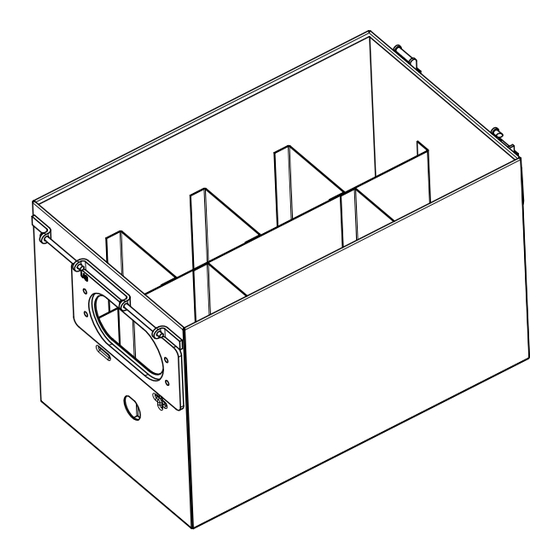
NOTE: The item numbers are those of the detailed parts list chapter (Refer to Detailed part list). 1656-6 Saft nickel-cadmium battery consists of a box (045), containing individual cells VP160KH. These cells are con- nected in series to obtain 24 V nominal. -
Page 24: Operation
Component Maintenance Manual 1656-6 The cover (020), which can be removed, is attached to the box (045) by 2 latches. Filling instruction plate Cover Connector Identification plate Amendement plate Figure 2 Nickel-Cadmium Aircraft Battery 4. Operation 4-1. climatic requirement Unless otherwise stated, charge and discharge testing should be done when the battery temperature is between + 15 °C and + 30 °C. -
Page 25: Rapid Partial Charge
1.5 A during 4 hours. If specific instructions are not given in the charger operating manual, you must first contact Saft. 24-31-19 Page 3 Dec 11/2017... - Page 26 Component Maintenance Manual 1656-6 PAGE INTENTIONALLY LEFT BLANK 24-31-19 BLANK Dec 11/2017...
-
Page 27: Testing And Fault Isolation
Component Maintenance Manual 1656-6 TESTING AND FAULT ISOLATION 1. Introduction This chapter gives the tests and inspections required to find the cause of faulty condition of the unit either removed for unsched- uled maintenance or during scheduled maintenance. The test procedure is given in the tables below. For each test refer to the indicated procedures which specify all necessary information. -
Page 28: Cell Faults
Component Maintenance Manual 1656-6 1-2. Cell faults Problem Probable cause Correction (1) Too much water decrease (a) Charge much more than the limit or Examine the cause of excessive charge. for all battery cells. too much charge at high temperature. - Page 29 Component Maintenance Manual 1656-6 1-3. Physical faults Problem Probable cause Correction (1) Leakage of electrolyte. (a) Incorrect adjustment of electrolyte Disassemble and clean the battery level. (refer to Disassembly Cleaning chapters). Do an electrolyte level check (refer to Inspection/check). (b) Cell polarity incorrect during high-...
- Page 30 Component Maintenance Manual 1656-6 PAGE INTENTIONALLY LEFT BLANK 24-31-19 BLANK Dec 11/2017...
- Page 31 Component Maintenance Manual 1656-6 DISASSEMBLY 1. Introduction NOTE: Refer to the Testing and fault isolation chapter to identify the possible cause of a malfunction. This will give the necessary level of disassembly. The instructions found in this section are designed to allow the maintenance person to completely disassemble the battery for the purpose of General Overhaul.
- Page 32 Component Maintenance Manual 1656-6 4-6. Disassembly of the battery Remove the cover (020) according to para. Removing the cover (020). Remove the connector (220) according to para. Removing the connector (220). NOTE: Note placement prior to removal to ensure proper placement during re-assembly.
- Page 33 1. Introduction The instructions in this chapter are for the general cleaning of your Saft aircraft battery. The instructions under “Light Cleaning” are to be done each time the battery is removed from the aircraft, and can be accomplished with no disassembly of the battery.
- Page 34 Component Maintenance Manual 1656-6 5-1-3. Nuts, spring washers and links Clean in lightly soapy water with a brush, rinse well with clean water and let dry. 5-1-4. Liner spacer kit (190) Clean in warm water and let dry. 5-1-5. Vent valve (180) Caution: The cleaning of the vent valve (180) must be done when the cells are assembled in the box.
- Page 35 1. Introduction 1-1. General This chapter includes the checks, the maintenance procedures and the functional tests that must be done to use Saft batteries in flight and on the ground. NOTE: All ( ) part identification numbers herein are IPL Fig. 1 item numbers.
- Page 36 Component Maintenance Manual 1656-6 6. Periodical check PERIODICAL CHECK Light Cleaning Visual Inspection Insulation check General overhaul Nut tightness U > 21 V no cell with reversed polarity Residual discharge Polarization test Vent valve cleaning (refer to Cleaning) Charge Adjust electro-...
- Page 37 Component Maintenance Manual 1656-6 Consult the airframe manufacturer for specific maintenance intervals or special procedures to be followed. Otherwise, at spe- cific intervals according to aircraft use, or if electrolyte consumption exceeds the approved consumption levels between 2 reg- ular checks, do this periodical check according to the above figure.
- Page 38 Component Maintenance Manual 1656-6 Leave the battery on open circuit for 1 hour. Measure the open circuit voltage of each cell. If any cell is zero (0) V or negative polarity, do a General overhaul. If all cells are above zero (0) V, continue with maintenance as specified.
- Page 39 Component Maintenance Manual 1656-6 - 4. Withdraw the plunger and check for any liquid in the syringe. Any excess liquid in the cell will be drawn into the syringe until the electrolyte is level with the end of the nozzle. This is the correct level for the electrolyte.
- Page 40 Component Maintenance Manual 1656-6 7. Regular check Light Cleaning REGULAR CHECK Visual Inspection Insulation check Nut tightness General overhaul U > 1.05 V/cell no cell with reversed polarity Polarization test Residual discharge Charge Cell shorting Adjust electrolyte level Charge Testing and fault isolation...
- Page 41 Component Maintenance Manual 1656-6 NOTE: Time periods are given as a guideline. Modify in accordance with operational experience. Periodic and Regular maintenance checks may be combined if operating hours permit. 7-1. Cell shorting As each cell’s voltage drops below 1.0 V, connect an equalizing resistor (T03) across each cell’s terminals. Leave the resistors in place for 12 to 16 hours to allow each cell to completely discharge and the battery to cool.
- Page 42 Component Maintenance Manual 1656-6 8. General overhaul On fault Scheduled GENERAL OVERHAUL U > 1.05 V/cell Polarization test Polarization test no cell with reversed polarity Nut tightness Residual discharge Charge Adjust electro- lyte level Cell shorting Charge Disassembly Testing and fault isolation...
- Page 43 NOTE: All cells that are changed must be replaced by a new Saft cell.. 8-2-2. Other components Any other components that are to be changed must be replaced by a new Saft component. 8-3. Sensor check Do this test in a climatic chamber with the sensor dissassembled from the battery. Check the sensor, according to the table...
- Page 44 Component Maintenance Manual 1656-6 - Test according to the table below, and change all vent valves that do not pass the test. test Check O-ring No distortion, split or cracks air pressure < 0.14 bar (2 psi) Vent valve is closed 0.14 bar (2 psi) <...
- Page 45 Component Maintenance Manual 1656-6 ASSEMBLY 1. Introduction This section covers basic battery assembly procedures. In all cases, when reassembling a battery, all components should be clean and dry. 2. Safety Refer to chapter Safety.. 3. Equipment 3-1. Standard tools Refer to chapter...
- Page 46 Component Maintenance Manual 1656-6 4-1. Installation of the liner spacer kit (190) K (1max) K (1 max) K (1max) K (1 max) K (1max) O (1 + 1 max) K (1 max) S (2 max) O (1 max) Figure 7001 Liner spacer kit installation - Put the differents spacers in position (Ref.
- Page 47 (if it is difficult to put in the last cell, remove one or two spacers). Verify the polarity of each cell accordingt to the figure 10001 1656-6 Nickel-Cadmium Aircraft Battery. Tighten and check the torque of all lower nuts (140) (refer to...
- Page 48 Component Maintenance Manual 1656-6 Install the cover complete (020) and attach it. 4-3. Installation of the vent valve (180) Make sure the vent valves (180) are in good condition. Replace the vent valves (180) if they are worn. Install the vent valve (180) with the universal vent wrench (T01).
- Page 49 Component Maintenance Manual 1656-6 4-4. Installation of the sensor (240) Install the sensor (240) in the box (045). Install the washer install the nut.) 4-5. Installation of the connector (220) Screw the connector (220) with the washer (210) and the screw (200).
- Page 50 Component Maintenance Manual 1656-6 PAGE INTENTIONALLY LEFT BLANK 24-31-19 BLANK Dec 11/2017...
- Page 51 Component Maintenance Manual 1656-6 FITS AND CLEARANCES 1. Introduction The torque values below are “lube torque” values. The thread of the terminals and attaching nuts (or screws) should be lightly greased with (M02) prior to assembly and applying torque. 2. Torque table...
- Page 52 Component Maintenance Manual 1656-6 PAGE INTENTIONALLY LEFT BLANK 24-31-19 BLANK Dec 11/2017...
- Page 53 Component Maintenance Manual 1656-6 SPECIAL TOOLS, FIXTURES, EQUIPMENT AND CONSUMABLES 1. Introduction This chapter is divided into two parts: - The first part provides the list of special tools, fixtures and equipments needed to do the steps listed in the other chapters.
- Page 54 NOTE: Equivalent tools can be used. A special tool kit (P/N 416161) is available from Saft containing all special tools T01, T02, T03, and T04. The tools are housed in a polypropylene box and each tool is insulated to ensure optimum safety for the technician.
- Page 55 Component Maintenance Manual 1656-6 ILLUSTRATED PARTS LIST 1. Introduction 1-1. General The Illustrated Parts List (IPL) contains a list and illustrations of the assemblies and detailed parts of the unit in disassembly sequence. To find the illustration for a part if the part number is known, refer to the...
- Page 56 Component Maintenance Manual 1656-6 When the effectivity is fully applicable, the usage code column remains blank. The use code for assemblies and detailed parts refers to the figure/item number of the next higher assembly (ies) or sub-as- sembly (ies). Example: Effectivity 1A, 1B, 1C is written 1ABC.
- Page 57 Component Maintenance Manual 1656-6 2. Alpha numerical index Airline Stock Figure Item Part Number Total required Number Number Number 1656-6 -001 012943 012944 013633 013678 014703 031282 034031 062000 062023 063417 100111 100430 100479 100523 100695 100696 102226 105405 106316...
- Page 58 Component Maintenance Manual 1656-6 3. Detailed part list : Polarity + : Polarity - 045 (010 with cover 020) Figure 10001 1656-6 Nickel-Cadmium Aircraft Battery 24-31-19 Page 10004 Dec 11/2017...
- Page 59 Num- Stock 1 2 3 4 5 6 7 Battery Number VP6177 -001 1656-6 BATTERY 1656-6, 410627 411736 . Box and cover, complete 410630 . . Cover, complete 106316 . . . Cover, assembly 106319 . . . Cover gasket 115737 .
- Page 60 Component Maintenance Manual 1656-6 Part Figure Item Airline Nomenclature Quantity per Number Num- Num- Stock 1 2 3 4 5 6 7 Battery Number VP6177 034031 . Plate, amendment 280068 . Plate, recycling - : item non illustrated 24-31-19 Page 10006...
- Page 61 - Isolated from detrimental agents: i.e. dirt, dust, dampness, vibration, corrosive atmosphere. Lead batteries must not be stored in the same room. Saft Ni-Cd batteries may be stored in temperatures ranging from -55 °C to +60 °C (-67 °F to +140 °F) for short periods of time without harming the battery.
- Page 62 Component Maintenance Manual 1656-6 3. Inactive stand-by storage 3-1. Definition the battery is charged after being serviced then stored fully charged in a dedicated room in such a way that it can be installed in the aircraft without further check. The battery may be kept in stand-by for the period corresponding to 80% available capacity on figure 15001 (for example 24 days at 30 °C) with a maximum of 90 days.
- Page 63 4. Active stand-by mode (= use of a trickle charge) CAUTION: water consumption. Principle: the battery is continuously charged, in an overcharge condition. Saft does not recommend this method, however some operators take responsibility for its use. This method is not reliable due to quantity and inaccuracy of water consumption.
- Page 64 According to the IATA / IMDG dangerous goods regulations, Saft ships all existing nickel-cadmium batteries or cells for aircraft under the classification UN2795 (wet, filled with alkali) according to packing instruction 800.
Need help?
Do you have a question about the 1656-6 and is the answer not in the manual?
Questions and answers