Table of Contents
Advertisement
Quick Links
USB3 Vision
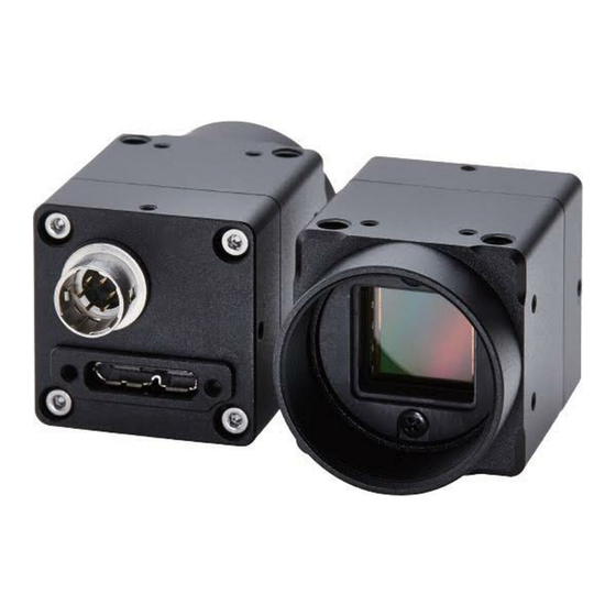
Monochrome / Color CMOS Camera
STC-MBS891U3V (8.9M / Monochrome / High speed)
STC-MCS891U3V (8.9M / Color / High speed)
STC-MBS123BU3V (12M / Monochrome / High speed)
STC-MCS123BU3V (12M / Color / High speed)
Product Specifications and Use's Guide
STC-MBS891U3V / STC-MCS891U3V / STC-MBS123BU3V / STC-MCS123BU3V
Product Specifications and Use's Guide
No.16S121-03
1/64
Advertisement
Table of Contents

Subscribe to Our Youtube Channel
Related Manuals for Omron STC-MBS891U3V


Summary of Contents for Omron STC-MBS891U3V
- Page 1 No.16S121-03 USB3 Vision Monochrome / Color CMOS Camera STC-MBS891U3V (8.9M / Monochrome / High speed) STC-MCS891U3V (8.9M / Color / High speed) STC-MBS123BU3V (12M / Monochrome / High speed) STC-MCS123BU3V (12M / Color / High speed) Product Specifications and Use’s Guide...
-
Page 2: Table Of Contents
4.5.2 IO Connector ............................22 4.5.3 Reference Input Circuit ........................23 4.5.4 Reference Output Circuit ........................24 Dimensions ......................25 Sensor Information .................... 26 Pixel Transferring Image ......................26 STC-MBS891U3V / STC-MCS891U3V / STC-MBS123BU3V / STC-MCS123BU3V 2/64 Product Specifications and Use’s Guide... - Page 3 Gain ............................45 9.6.1 Analog Gain ............................45 9.6.2 Digital Gain ............................45 9.6.3 White Balance Gain (Only available for the color model) ..............45 Black Level..........................46 STC-MBS891U3V / STC-MCS891U3V / STC-MBS123BU3V / STC-MCS123BU3V 3/64 Product Specifications and Use’s Guide...
- Page 4 9.17.6 CounterAndTimerControl ........................59 9.17.7 EventControl ............................60 9.17.8 EventExposureEndData ........................60 9.17.9 EventExposureStartData ........................60 9.17.10 EventTestData ..........................60 9.17.11 AnalogControl ..........................61 9.17.12 LUTControl ............................61 STC-MBS891U3V / STC-MCS891U3V / STC-MBS123BU3V / STC-MCS123BU3V 4/64 Product Specifications and Use’s Guide...
- Page 5 No.16S121-03 9.17.13 UserSetControl ..........................61 9.17.14 ChunkDataControl .......................... 62 9.17.15 TestControl ............................62 10 Revision History ....................63 STC-MBS891U3V / STC-MCS891U3V / STC-MBS123BU3V / STC-MCS123BU3V 5/64 Product Specifications and Use’s Guide...
- Page 6 Do not wrong wiring. that is specified in the specifications for this This will cause of fire or malfunction. camera. This will cause of fire, electrification or malfunction. STC-MBS891U3V / STC-MCS891U3V / STC-MBS123BU3V / STC-MCS123BU3V 6/64 Product Specifications and Use’s Guide...
- Page 7 Do not block the radiation holes. the camera. This will cause of fire due to increase the This will cause of electrification or malfunction. camera inside temperature. STC-MBS891U3V / STC-MCS891U3V / STC-MBS123BU3V / STC-MCS123BU3V 7/64 Product Specifications and Use’s Guide...
- Page 8 It is turn off the camera when maintaining or This will cause of fire, electrification or inspecting the camera. malfunction. This will cause of electrification. [Disposal] Caution It is necessary to dispose as industrial waste. STC-MBS891U3V / STC-MCS891U3V / STC-MBS123BU3V / STC-MCS123BU3V 8/64 Product Specifications and Use’s Guide...
-
Page 9: Product Precautions
Exchange or repair the malfunction camera if the malfunction is occurred by our responsibility. “Warranty” mean is warranty for the delivered camera itself. Please accept the induction damage by the camera malfunction is not included. STC-MBS891U3V / STC-MCS891U3V / STC-MBS123BU3V / STC-MCS123BU3V 9/64 Product Specifications and Use’s Guide... -
Page 10: Overview
Product Number Naming Method STC-MxS891U3V U3V: USB3 Vision 891: 8.9M pixels, 1”, High speed sensor 123B: 12M pixels, 1.1”, High speed sensor Sensor Manufacturer S: SONY B: Monochrome C: Color STC-MBS891U3V / STC-MCS891U3V / STC-MBS123BU3V / STC-MCS123BU3V 10/64 Product Specifications and Use’s Guide... -
Page 11: Specifications
Horizontal: x2 / Off, Vertical: x2 / Off (select individually) (Horizontal: Average, Vertical: Addition) (*2) Decimation Horizontal: x2 / Off, Vertical: x2 / Off (select individually) Default: Bold STC-MBS891U3V / STC-MCS891U3V / STC-MBS123BU3V / STC-MCS123BU3V 11/64 Product Specifications and Use’s Guide... -
Page 12: Stc-Mbs123Bu3V / Stc-Mcs123Bu3V
+5 V (typ.) (This conforms to the USB standard) / +8.0 to +24 V External power (via 6 pin connector) * Recommend with external power (*4) Consumption (*3) Maximum: 5.7 W, Typical: 4.7 W Default: Bold STC-MBS891U3V / STC-MCS891U3V / STC-MBS123BU3V / STC-MCS123BU3V 12/64 Product Specifications and Use’s Guide... - Page 13 Horizontal: x2 / Off, Vertical: x2 / Off (select individually) Image Flip Horizontal / Vertical / Horizontal and Vertical / Off Pixel Defect Correction Up to 256 points Default: Bold STC-MBS891U3V / STC-MCS891U3V / STC-MBS123BU3V / STC-MCS123BU3V 13/64 Product Specifications and Use’s Guide...
- Page 14 +5 V (typ.) (This conforms to the USB standard) / +8.0 to +24 V External power (via 6 pin connector) * Recommend with external power (*4) Consumption (*3) Maximum: 6.0 W, Typcal: 5.0 W Default: Bold STC-MBS891U3V / STC-MCS891U3V / STC-MBS123BU3V / STC-MCS123BU3V 14/64 Product Specifications and Use’s Guide...
- Page 15 PC resources may have consumed during the image processing (color interpolation, image display, etc.) and the frame rate becomes slower due to transfer and processing huge image data. STC-MBS891U3V / STC-MCS891U3V / STC-MBS123BU3V / STC-MCS123BU3V 15/64 Product Specifications and Use’s Guide...
-
Page 16: Spectral Sensitivity Characteristics
No.16S121-03 Spectral Sensitivity Characteristics STC-MBS891U3V / STC-MCS891U3V / STC-MBS123BU3V / STC-MCS123BU3V 16/64 Product Specifications and Use’s Guide... - Page 17 No.16S121-03 STC-MBS891U3V / STC-MCS891U3V / STC-MBS123BU3V / STC-MCS123BU3V 17/64 Product Specifications and Use’s Guide...
- Page 18 No.16S121-03 STC-MBS891U3V / STC-MCS891U3V / STC-MBS123BU3V / STC-MCS123BU3V 18/64 Product Specifications and Use’s Guide...
-
Page 19: Stc-Mcs891U3V (Without Ir Cut Filter)
M4 screws holes (Four on top, bottom and both side plate) Weight Approximately 78 g (*1) excluding the connectors (*2) Recommend lens: More than F2.8 (Close side) STC-MBS891U3V / STC-MCS891U3V / STC-MBS123BU3V / STC-MCS123BU3V 19/64 Product Specifications and Use’s Guide... -
Page 20: Environmental Specifications
72 deg. C, the camera housing temperature (top plate) will be less than 63 deg. C. Taking these steps will maintain the heat rating of the electronic components of the camera. Upper side of camera Measuring point STC-MBS891U3V / STC-MCS891U3V / STC-MBS123BU3V / STC-MCS123BU3V 20/64 Product Specifications and Use’s Guide... -
Page 21: External Connector Specifications
USB OTG ID SSTX− SuperSpeed transmitter differential pair (−) SSTX+ SuperSpeed transmitter differential pair (+) SSRX− SuperSpeed receiver differential pair (−) SSRX+ SuperSpeed receiver differential pair (+) 12345 678910 STC-MBS891U3V / STC-MCS891U3V / STC-MBS123BU3V / STC-MCS123BU3V 21/64 Product Specifications and Use’s Guide... - Page 22 (*3): When the external IO port is connected, control the current less than 15 mA on the IO port. (*4): This value is the typical current value of the Input Port when High Voltage is input. STC-MBS891U3V / STC-MCS891U3V / STC-MBS123BU3V / STC-MCS123BU3V 22/64...
-
Page 23: Reference Input Circuit
USER INPUT USER_INPUT Internal Voltage 内部電圧 Camera internal カメラ内部 IO_GND IO_GND Capable input trigger’s pulse width is Positive Trigger: More than tIPDLH Negative Trigger: More than tIPDHL STC-MBS891U3V / STC-MCS891U3V / STC-MBS123BU3V / STC-MCS123BU3V 23/64 Product Specifications and Use’s Guide... -
Page 24: Reference Output Circuit
2.68 μseconds 2.61 μseconds tOPDLH tOPDHL Internal Voltage 内部電圧 Camera internal カメラ内部 USER_OUTPUT +3.3V or VCCext 3.3VまたはVCCext USER OUTPUT IO_GND IO_GND (*1) Measured on +3.3V internal Voltage. STC-MBS891U3V / STC-MCS891U3V / STC-MBS123BU3V / STC-MCS123BU3V 24/64 Product Specifications and Use’s Guide... -
Page 25: Dimensions
No.16S121-03 Dimensions Unit: mm STC-MBS891U3V / STC-MCS891U3V / STC-MBS123BU3V / STC-MCS123BU3V 25/64 Product Specifications and Use’s Guide... -
Page 26: Sensor Information
Pixel (n) of Data: nth pixel being transferred STC-MCS891U3V / STC-MCS123BU3V (Color) Pixel00 Pixel01 Data Data Pixel11 Pixel10 Data Data Pixel (m, n) of Data: nth pixel of the mth line being transferred STC-MBS891U3V / STC-MCS891U3V / STC-MBS123BU3V / STC-MCS123BU3V 26/64 Product Specifications and Use’s Guide... -
Page 27: Image Acquisition And Camera Operational Modes (Genicam)
When Exposure Mode is set to Timed, the Exposure Time value will be set as the exposure time. ExposureTime 露光 Exposure Image Out 映像出力 (*) The camera is set to Free run mode as the default mode. STC-MBS891U3V / STC-MCS891U3V / STC-MBS123BU3V / STC-MCS123BU3V 27/64 Product Specifications and Use’s Guide... -
Page 28: Trigger Mode
Controlled, camera exposure and image acquisition do not work. (*) Please do not apply the Trigger through maximum frame rate on Trigger Mode. When Trigger applies within sensor Readout as exposure end, camera interrupted Readout. STC-MBS891U3V / STC-MCS891U3V / STC-MBS123BU3V / STC-MCS123BU3V 28/64 Product Specifications and Use’s Guide... -
Page 29: Frame Start Trigger (Edge Preset)
0 to 12.73 0 to 10.51 10bits Packed 0 to 8.22 0 to 6.94 12bits 0 to 12.73 0 to 10.51 12bits Packed 0 to 9.41 0 to 7.92 STC-MBS891U3V / STC-MCS891U3V / STC-MBS123BU3V / STC-MCS123BU3V 29/64 Product Specifications and Use’s Guide... -
Page 30: Frame Start Trigger (Pulse Width Trigger)
0 to 12.73 0 to 10.51 10bits Packed 0 to 8.22 0 to 6.94 12bits 0 to 12.73 0 to 10.51 12bits Packed 0 to 9.41 0 to 7.92 STC-MBS891U3V / STC-MCS891U3V / STC-MBS123BU3V / STC-MCS123BU3V 30/64 Product Specifications and Use’s Guide... -
Page 31: Exposure Start Trigger, Exposure End Trigger
This function can apply either external signal or a software command as the trigger. The software trigger can be applied through the “execute Trigger Software” command when the trigger is selected on the Trigger Selector. STC-MBS891U3V / STC-MCS891U3V / STC-MBS123BU3V / STC-MCS123BU3V 31/64 Product Specifications and Use’s Guide... -
Page 32: Io Function
This function monitors the signal status on the input Line. The High level (Line Status: true) or Low level (Line Status false) status can be seen through the software. STC-MBS891U3V / STC-MCS891U3V / STC-MBS123BU3V / STC-MCS123BU3V 32/64 Product Specifications and Use’s Guide... -
Page 33: Line Debouncer
This Trigger Delay can add to the duration per μsecond GenICam Parameters TriggerDelay Integer Type Trigger Delay Range: 0 to 262,143 μseconds, Default: 0 μsecond STC-MBS891U3V / STC-MCS891U3V / STC-MBS123BU3V / STC-MCS123BU3V 33/64 Product Specifications and Use’s Guide... -
Page 34: Output Port Function
8) Exposure Active (In Exposure Period) The signal that activation time is exposure time is output. (*) Actual exposure period = Output signal pulse width + Minimum exposure time 13.73 seconds μ STC-MBS891U3V / STC-MCS891U3V / STC-MBS123BU3V / STC-MCS123BU3V 34/64 Product Specifications and Use’s Guide... - Page 35 (*) The trigger port in this chart describes Frame Start trigger as an example (*) Trigger Out and Strobe Out do not output from the camera for Exposure Start trigger and Exposure End trigger STC-MBS891U3V / STC-MCS891U3V / STC-MBS123BU3V / STC-MCS123BU3V 35/64 Product Specifications and Use’s Guide...
-
Page 36: User Output
The hardware reset can be done by CAM_RESET port. Sets On (Default: Off) at Line Device Reset Mode, and apply the Low voltage in 5 seconds on CAM_RESET port then camera rest. STC-MBS891U3V / STC-MCS891U3V / STC-MBS123BU3V / STC-MCS123BU3V 36/64 Product Specifications and Use’s Guide... -
Page 37: Camera Functions
Setting steps: 4 lines The parameters define as following chart. OffsetY Height ROI Region OffsetX Width (*) Width, Height, OffsetX, OffestY setting steps is the same in Binning and Decimation. STC-MBS891U3V / STC-MCS891U3V / STC-MBS123BU3V / STC-MCS123BU3V 37/64 Product Specifications and Use’s Guide... - Page 38 (*) 64 pixels unit on Packed output Height Setting range: 32 to 2,160 lines 32 to 3,000 lines Default: 2,160 lines 3,000 lines Setting steps 4 lines 4 lines STC-MBS891U3V / STC-MCS891U3V / STC-MBS123BU3V / STC-MCS123BU3V 38/64 Product Specifications and Use’s Guide...
-
Page 39: Multi Roi
Region5 Region6 Region7 OffsetX [Region2] Region8 Region9 Region10 Region11 OffsetX [Region3] Region12 Region13 Region14 Region15 Multi ROI can be configuring 16 regions as Region 0 to 15. STC-MBS891U3V / STC-MCS891U3V / STC-MBS123BU3V / STC-MCS123BU3V 39/64 Product Specifications and Use’s Guide... - Page 40 Region8 OffsetX [Region2] Region7 Region6 Region5 Region4 OffsetX [Region1] Width[Region3] Width[Region2] Width[Region0] Width[Region1] Region3 Region2 Region1 Region0 OffsetX [Region0] OffsetY OffsetY OffsetY OffsetY [Region12] [Region0] [Region8] [Region4] STC-MBS891U3V / STC-MCS891U3V / STC-MBS123BU3V / STC-MCS123BU3V 40/64 Product Specifications and Use’s Guide...
-
Page 41: Pixel Format
1: Disable Binning 2: Binning 2 Pixel BinningVertical Integer Type Sets Binning on Vertical direction 1: Disable Binning 2: Binning 2 Pixel (*) Binning and Decimation function cannot be use simultaneously. STC-MBS891U3V / STC-MCS891U3V / STC-MBS123BU3V / STC-MCS123BU3V 41/64 Product Specifications and Use’s Guide... -
Page 42: Decimation
1: Disable Decimation, 2: Decimate one of two pixels DecimationVertical Integer Type Sets decimation on vertical direction 1: Disable Decimation, 2: Decimate one of two pixels (*) Binning and Decimation function cannot be use simultaneously. STC-MBS891U3V / STC-MCS891U3V / STC-MBS123BU3V / STC-MCS123BU3V 42/64 Product Specifications and Use’s Guide... -
Page 43: Image Flip
Switch ON / OFF at Vertical False: Vertical Flip Off, True: Vertical Flip On. Default: False Reverse X(Off), Y(Off) Reverse X(Off), Y(On) Reverse X(On), Y(Off) Reverse X(On), Y(On) STC-MBS891U3V / STC-MCS891U3V / STC-MBS123BU3V / STC-MCS123BU3V 43/64 Product Specifications and Use’s Guide... - Page 44 Reverse X(Off), Y(Off) Reverse X(Off), Y(On) Reverse X(On), Y(Off) Reverse X(On), Y(On) (*) When the image is flipping for color camera, the pixel array is also flipped. STC-MBS891U3V / STC-MCS891U3V / STC-MBS123BU3V / STC-MCS123BU3V 44/64 Product Specifications and Use’s Guide...
-
Page 45: Gain
IFloat Type White Balance Gain Range: 0 to 511, Default: Red: 229, Green: 128, Blue: 272 White Balance Gain Formula Gain (x times) = BalanceRatio[BalanceRatioSelector] / 128 STC-MBS891U3V / STC-MCS891U3V / STC-MBS123BU3V / STC-MCS123BU3V 45/64 Product Specifications and Use’s Guide... -
Page 46: Black Level
When AGC and auto exposure are enabled, at first, the brightness adjust with auto exposure function. If the brightness does not achieve “Auto Light Target” brightness with auto exposure function, the brightness adjusts with the AGC function. STC-MBS891U3V / STC-MCS891U3V / STC-MBS123BU3V / STC-MCS123BU3V 46/64 Product Specifications and Use’s Guide... -
Page 47: Agc (Auto Gain Control)
Sets “Exposure Auto Limit Min” (When using Auto Exposure) Sets “Continuous” at “Gain Auto” (When using AGC) Sets “Gain Auto Limit Max” (When using AGC) Sets “Gain Auto Limit Min” (When using AGC) STC-MBS891U3V / STC-MCS891U3V / STC-MBS123BU3V / STC-MCS123BU3V 47/64 Product Specifications and Use’s Guide... -
Page 48: White Balance (Only Available For The Color Model)
Sets value at “Balance Ratio” Sets “Off” at “Balance White Auto” Optimizes white balance gain each frame automatically. Setting Procedure 1. Sets “Continuous” at “Balance White Auto” STC-MBS891U3V / STC-MCS891U3V / STC-MBS123BU3V / STC-MCS123BU3V 48/64 Product Specifications and Use’s Guide... -
Page 49: Push To Set White Balance (Once)
Sets “Off” at “Balance White Auto” automatically after set “White Balance Gain”. Setting Procedure Sets the flat white target (To process white balance correctly) Sets Once on Balance White Auto STC-MBS891U3V / STC-MCS891U3V / STC-MBS123BU3V / STC-MCS123BU3V 49/64 Product Specifications and Use’s Guide... -
Page 50: Gamma Table
3072 Gamma Table 2560 2048 Generate by the linear interpolation with A point 1536 and B point. 1024 1024 1536 2048 2560 3072 3584 4096 Input data STC-MBS891U3V / STC-MCS891U3V / STC-MBS123BU3V / STC-MCS123BU3V 50/64 Product Specifications and Use’s Guide... -
Page 51: Save And Load The Camera Settings
ROM that is selected at Setting UserSetSelector. Caution: Default Selector UserSetSave cannot execute when “Default” was selected at “UserSet Selector” UserSetSelector Setting Procedure 1. Selects “UserSetX” at “UserSetSelector” 2. Execute “UserSetSave” STC-MBS891U3V / STC-MCS891U3V / STC-MBS123BU3V / STC-MCS123BU3V 51/64 Product Specifications and Use’s Guide... -
Page 52: Loading Camera Settings
Set “UserSetX” or “Default” at “UserSetDefault” Please follow the below procedure for the camera settings put back to the factory default settings. Setting Procedure Selects “Default” at “UserSetSelector”. Executes “UserSetLoad”. STC-MBS891U3V / STC-MCS891U3V / STC-MBS123BU3V / STC-MCS123BU3V 52/64 Product Specifications and Use’s Guide... -
Page 53: Pixel Defect Correction
When the external hardware or software signal is input to the camera, the following process are proceeding. Line0 Line Line1 Debouncer Trigger Trigger トリガー Trigger Selector Delay Line2 Software Trigger Trigger Source STC-MBS891U3V / STC-MCS891U3V / STC-MBS123BU3V / STC-MCS123BU3V 53/64 Product Specifications and Use’s Guide... -
Page 54: Device User Id
Send notification as event when expose finishes in the camera. Event ID is 0x9001. (*) The event occurrence frequently, the stream data transferring rate could be reduced because Event and Stream (image data) share USB bus. STC-MBS891U3V / STC-MCS891U3V / STC-MBS123BU3V / STC-MCS123BU3V 54/64 Product Specifications and Use’s Guide... -
Page 55: Chunk Control (Only Available With Usb3 Vision Protocol)
Transfer the exposure time when image was acquiring, as Chunk data. Chunk ID is 0x00000004. Chunk Gamma Transfer the Gamma when image was acquiring, as Chunk data. Chunk ID is 0x00000005. STC-MBS891U3V / STC-MCS891U3V / STC-MBS123BU3V / STC-MCS123BU3V 55/64 Product Specifications and Use’s Guide... -
Page 56: Genicam Command List
DeviceLinkCommandTimeout Indicates the command timeout of the specified Link. This corresponds to the maximum response time of the device for a command sent on that link. STC-MBS891U3V / STC-MCS891U3V / STC-MBS123BU3V / STC-MCS123BU3V 56/64 Product Specifications and Use’s Guide... -
Page 57: Imageformatcontrol
Width of the image provided by the device (in pixels). Height Height of the image provided by the device (in pixels). OffsetX Horizontal offset from the origin to the region of interest (in pixels). STC-MBS891U3V / STC-MCS891U3V / STC-MBS123BU3V / STC-MCS123BU3V 57/64 Product Specifications and Use’s Guide... -
Page 58: Acquisitioncontrol
Determine the upper limit of exposure time when ExposureAuto is set to Continuous. ExposureAutoLimitMin Determine the lower limit of exposure time when ExposureAuto is set to Continuous. STC-MBS891U3V / STC-MCS891U3V / STC-MBS123BU3V / STC-MCS123BU3V 58/64 Product Specifications and Use’s Guide... -
Page 59: Transportlayercontrol
Returns the current status of the Counter. CounterTriggerSource Selects the source to start the Counter. CounterTriggerActivation Selects the activation mode of the trigger to start the Counter. STC-MBS891U3V / STC-MCS891U3V / STC-MBS123BU3V / STC-MCS123BU3V 59/64 Product Specifications and Use’s Guide... -
Page 60: Eventcontrol
Its value uniquely identifies the type of event that will be received. EventTestTimestamp Returns the timestamp of the Test event. STC-MBS891U3V / STC-MCS891U3V / STC-MBS123BU3V / STC-MCS123BU3V 60/64 Product Specifications and Use’s Guide... -
Page 61: Analogcontrol
Save the User Set specified by UserSetSelector to the non-volatile memory of the UserSetSave device. UserSetDefault Selects the feature User Set to load and make active by default when the device is reset. STC-MBS891U3V / STC-MCS891U3V / STC-MBS123BU3V / STC-MCS123BU3V 61/64 Product Specifications and Use’s Guide... - Page 62 TestPendingAck before acknowledging the write. TestEventGenerate Generates a Test Event. TriggerEventTest This register is used to control the generation of test events. STC-MBS891U3V / STC-MCS891U3V / STC-MBS123BU3V / STC-MCS123BU3V 62/64 Product Specifications and Use’s Guide...
- Page 63 Added trademark information USB3 Vision is trademark of AIA. GenICam is trademark of EMVA. Other company names and product names in this document are trademarks of their respective owners. STC-MBS891U3V / STC-MCS891U3V / STC-MBS123BU3V / STC-MCS123BU3V 63/64 Product Specifications and Use’s Guide...
- Page 64 No.16S121-03 19F, Ebina Prime Tower 9-50, Chuo 2 chome Ebina-city, Kanagawa 243-0432 Japan TEL +81-46-236-6660 FAX +81-46-236-6661 URL http://www.sentech.co.jp/ STC-MBS891U3V / STC-MCS891U3V / STC-MBS123BU3V / STC-MCS123BU3V 64/64 Product Specifications and Use’s Guide...
Need help?
Do you have a question about the STC-MBS891U3V and is the answer not in the manual?
Questions and answers