Table of Contents
Advertisement
Quick Links
Contents
Important User Information . . . . . . . . . . . . . . . . . . . . . . . . . . . . . . 2
General . . . . . . . . . . . . . . . . . . . . . . . . . . . . . . . . . . . . . . . . . 2
Manufacturer . . . . . . . . . . . . . . . . . . . . . . . . . . . . . . . . . . . . . 2
Intended Use . . . . . . . . . . . . . . . . . . . . . . . . . . . . . . . . . . . . . 2
Warranty . . . . . . . . . . . . . . . . . . . . . . . . . . . . . . . . . . . . . . . . 2
Visit the Essential Lab Workstation web page at wengercorp.com for more information.
Note: Please read and understand these instructions before starting the assembly.
Note: If you need additional information, contact Wenger Corporation using the information below.
©Wenger Corporation 2022
Wenger Corporation, 555 Park Drive, P.O. Box 448, Owatonna, Minnesota 55060-0448
USA: (800) 4WENGER (493-6437) • Worldwide: +1-507-455-4100 • wengercorp.com
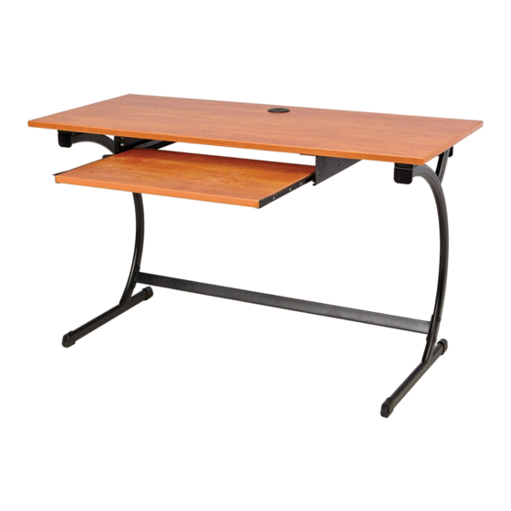
Essential Lab Workstation
Required Tools. . . . . . . . . . . . . . . . . . . . . . . . . . . . . . . . . . . . . . . . 3
Hardware Parts List . . . . . . . . . . . . . . . . . . . . . . . . . . . . . . . . . . . . 3
Assembly . . . . . . . . . . . . . . . . . . . . . . . . . . . . . . . . . . . . . . . . . . . . 4
Printed in USA 2022-06
Assembly Instructions
Part #256A113-03
Advertisement
Table of Contents

Subscribe to Our Youtube Channel
Related Manuals for Wenger Essential Lab

Summary of Contents for Wenger Essential Lab
-
Page 1: Table Of Contents
Warranty ........2 Visit the Essential Lab Workstation web page at wengercorp.com for more information. -
Page 2: Important User Information
Wenger Corporation. Wenger Corporation does not assume any responsibility for any errors that may appear in these instructions. In no event will Wenger Corporation be liable for technical or editorial omissions made herein, nor for direct, indirect, special, incidental, or consequential damages resulting from the use or defect of these instructions. -
Page 3: Required Tools
Required Tools • Phillips head screwdriver • 3/16" Allen wrench (supplied) • 3/8" & 7/16" Open-end wrenches, or sockets • 5/32" Allen wrench (supplied) Hardware Parts List #10-16 x 3/4" 1/4-20 x 1/2" 1/4-20 x 5/8" 1/4-20 x .590" 1/4-20 Pan Head Screw Carriage Bolt Truss Head Screw... -
Page 4: Assembly
Assembly 1. Lay the desktop flat on the ground with the pilot holes facing up. Be careful not to scratch the desktop surface! 2. Attach the legs to the bottom of the desktop in the orientation shown below. a. If including the optional spacer tubes (#13), attach the legs and spacer tubes to the desktop pilot holes using six #10-16 x 1.75"... - Page 5 Assembly (continued) 3. Attach the leg cross member to both legs using two 1/4-20 x .590" machine screws (#3) and 1/4-20 cap nuts (#5). Leg Cross Member 1/4-20 x .590 1/4-20 Machine Screws (#3) Cap Nuts (#4) 4. Attach the stiffener to the rear desktop pilot holes using eight #10-16 x 3/4" pan head screws (#2) as shown. #10 x 3/4"...
- Page 6 Assembly (continued) 5. With the glides facing the inside, attach both keyboard brackets to the desktop pilot holes using six #10-16 x 3/4" pan head screws (#2) in each as shown. #10 x 3/4" Pan Head Screws (#2) Left Hand Keyboard Bracket Right Hand...
- Page 7 Assembly (continued) 7. If attaching the optional power strip: a. Clean the surfaces of the power strip and the stiffener. b. Remove the backing from one side of the double-sided tape (16) and apply it to the back side of the power strip. Note: Foam tape is difficult to remove once set. Be sure of location before pressing in place. c. Remove the backing from the other side of the double-sided tape and mount the power strip to the stiffener as shown.
- Page 8 Assembly (continued) 9. Turn the assembly over. If attaching the optional CPU holder: a. Assemble the CPU holder according to the manufacturer's instructions. b. Attach the CPU holder to the nut inserts in the desktop with four 1/4-20 x 5/8" truss head screws (#5) as shown.
Need help?
Do you have a question about the Essential Lab and is the answer not in the manual?
Questions and answers