Advertisement
Quick Links
Advertisement

Related Manuals for Ludlum Measurements 4906AB


Summary of Contents for Ludlum Measurements 4906AB
- Page 1 ...
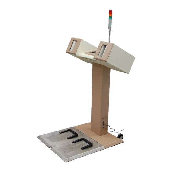
- Page 2 Model 4906AB System Checkout 1. Prerequisites a. Assembly i. The procedure presented here is for the checkout of a fully assembled Model 4906AB Hand and Foot Monitor. Before performing this procedure, ensure the unit is fully assembled. Page 2...
- Page 3 Model 4906AB System Checkout b. Power Supply i. Verify that the Model 4906AB unit is connected to the required power supply. Reference the Model 4906 Operator’s Manual for power specifications. c. Gas Supply i. Verify the Model 4906AB unit is connected to the required detection gas supply.
-
Page 4: Needed Equipment
Model 4906AB System Checkout 2. Needed Equipment a. Keyboard i. To perform the Model 4906AB Hand and Foot Monitor system checkout procedure, a USB keyboard is recommended for software interface and data entry. 3. Visual Inspection a. Physical Damage i. Perform a thorough visual inspection for physical unit damage. Take particular note of displays, covers, wires, indicator lights, and sensors. - Page 5 Model 4906AB System Checkout Page 5...
- Page 6 Model 4906AB System Checkout ii. Verify the Model 4906AB Unit is marked with a unit serial number. This number is stamped into the Power IO Panel located on the lower side portion of the column. The number is in the format XXXXXX (example 344628).
-
Page 7: Power On/Off Test
Model 4906AB System Checkout 4. Power ON/OFF Test a. The following power on/off tests are used to verify the Model 4906AB power cycle functions are working correctly. b. Power ON with Power Button i. Power on the unit by pressing and releasing the POWER/RESET button located on the power IO panel. - Page 8 To ensure reported accuracy and detector traceability, the serial number on each detector must be verified to match the serial number entered into the Model 4906AB Supervisor software for the appropriate position. If the detector serial numbers have not yet been entered in the software, enter the serial numbers at this time.
- Page 9 From the Setup menu, select the Operational button to bring up the Operational Setting screen. Select the General tab and verify/enter the Model 4906AB unit serial number and click the Apply button. Page 9...
- Page 10 Model 4906AB System Checkout Page 10...
- Page 11 Model 4906AB System Checkout 6. SBC to Host Communication a. To ensure proper Model 4906AB operation, the SBC must communicate to the Host board via a special USB-to-serial data cable, verifying Host-to-SBC communication is done by noting the absence of a hardware communication system failure.
- Page 12 Model 4906AB System Checkout c. If a hardware communication error state does exist, the Supervisor COM port setting must be verified. This can be done by navigating to the Setup menu (click Setup then enter the high-level password). d. Next, select the Operational button to view the Operational Settings screen.
- Page 13 7. Firmware Number Verification a. To verify that communication between the host board, SBC, and detector boards, firmware numbers displayed by the Model 4906AB Supervisor software must be verified to be valid. b. Start with the host board firmware number. Navigate to the Setup menu by selecting the Setup button on the Operate (Main) Screen.
- Page 14 Model 4906AB System Checkout d. Verify the host firmware number is a valid host firmware number. A valid firmware number for the host looks similar to “420275R01N01.” The “01” following the “R” and “N” must both be valid numbers greater than zero, not “??”...
- Page 15 Model 4906AB System Checkout h. Verify the frisker firmware number is a valid frisker detector board firmware number. A valid frisker detector board firmware number looks similar to “420427R01N01.” The “01” following the “R” and “N” must both be valid numbers greater than zero, not “??”...
- Page 16 Model 4906AB System Checkout b. Test the following user input/output devices as described. i. Alarm Light • Click the Turn On button in the Outputs group directly above the Alarm Off indicator bar • Verify the button text changes to Turn Off •...
- Page 17 Model 4906AB System Checkout iv. Left Hand Sensor • Place your left hand (or some other object) inside the left hand detector box • Verify the Left Hand Sensor Clear indicator bar changes from gray to orange, and the text changes from Left Hand Sensor Clear to Left Hand Sensor Blocked •...
- Page 18 One Hand Button • Press and release the One Hand button on the Model 4906AB main cabinet • Verify the One Hand Button Not Pressed indicator bar changes from gray to blue, and the text changes to One Hand Button Pressed •...
- Page 19 Model 4906AB System Checkout ix. Alarm Acknowledge Button • Press and release the Alarm Ack (Acknowledge) button on the Model 4906AB main cabinet • Verify the Alarm Ack Button Not Pressed indicator bar changes from gray to red, and the text changes to Alarm Ack Button Pressed •...
-
Page 20: Gas Flow Test
Model 4906AB System Checkout 9. Gas Flow Test a. Communication Test i. To determine if the Model 4906 host board is properly communicating with the Gas Control board, verify the Gas Control board firmware number is valid. ii. Navigate to the Gas Control Setup screen. Start by clicking the Setup button from the Main (Operate) screen and entering the high-level password (default = 2222) to view the Setup menu. - Page 21 Model 4906AB System Checkout b. Setup Test Values i. The Gas Control Setup screen has three tabs for setting up the gas control values. These tabs are Timing, Thresholds, and Errors. ii. Set the values for testing gas flow on each tab as listed below iii.
-
Page 22: Function Test
The flow in each circuit can be viewed from the General tab on the Gas Control Setup screen. Tilt the Model 4906AB monitor down for easier viewing of flow value while adjusting the valves. Flow rates on the screen update once every 2 seconds, and the system takes a few seconds to equalize from changes, so slow incremental adjustments are the best. - Page 23 Model 4906AB System Checkout v. Next, click the Purge Now button to initiate a gas purge. Page 23...
- Page 24 Model 4906AB System Checkout vi. Verify the Mode changes from GasOn to GasPurge. vii. Verify the Input and Output flow readings for each circuit increase drastically (generally to 250 or very close). viii. Wait two minutes for the purge to end and verify the mode changes from GasPurge back to GasOn and that the flow levels return to their previous settings after a few minutes of settling time.
- Page 25 Model 4906AB System Checkout iii. Errors • Additional Gas Source Error = 20 • Gas Leak Error = 30 • High Gas Flow Error = 30 • Low Gas Flow Error = 30 iv. Thresholds • Minimum Gas Flow Threshold = 10 SCCM •...
- Page 26 Model 4906AB System Checkout 10. Calibration and Detector Testing a. Factory Calibration and Checkout i. Once the above system checkout procedures are complete, the Model 4906 Calibration procedure must be completed, and collected data stored electronically and printed for shipment with the unit.
- Page 27 Model 4906AB System Checkout b. Create a Windows Restore Point i. Creating a Windows restore point is required when performing a factory calibration and checkout. Creating a restore point is also recommended any time a software or driver update is performed.
Need help?
Do you have a question about the 4906AB and is the answer not in the manual?
Questions and answers