ELTEX NTU-RG-5402G-W User Manual
Optical network terminals
Hide thumbs
Also See for NTU-RG-5402G-W:
- Operational manual (44 pages) ,
- User manual (59 pages) ,
- User manual (69 pages)
Advertisement
Quick Links
FW 2.3.0 NTU-RG-54xx. User manual (user)
Optical network terminals
NTU-RG-5402G-W
NTU-RG-5421G-Wac
NTU-RG-5421GC-Wac
NTU-RG-5421G-WZ
NTU-RG-5440G-WZ
NTU-RG-5440G-Wac
Firmware version 2.1.0 (07.2020)
IP address:
http://192.168.1.1
Login: user
Password: user
Introduction
A GPON is a network of passive optical networks (PON) type. It is one of the most effective state-of-the-art solutions of the last mile issue that enables
cable economy and provides information transfer downlink rate up to 2.5 Gbps and uplink rate up to 1.25 Gbps. Being used in access networks, GPON-
based solutions allow end users to have access to new services based on IP protocol in addition to more common ones.
The key GPON advantage is the use of one optical line terminal (OLT) for multiple optical network terminals (ONT). OLT converts Gigabit Ethernet and
GPON interfaces and is used to connect a PON network with data communication networks of a higher level. ONT device is designed to connect user
terminal equipment to broadband access services. It can be used in residential areas and office buildings.
The range of ONT NTU equipment produced by ELTEX comprises of terminals with four UNI interfaces of 10/100/1000Base-T and supports for FXS , Wi-
2
3
Fi, USB, Z-Wave , RF :
NTU-RG-5402G-W, NTU-RG-5421G-Wac, NTU-RG-5421GC-Wac, NTU-RG-5421G-WZ, NTU-RG-5440G-WZ, NTU-RG-5440G-Wac
This user manual describes intended use, main specifications, configuration, monitoring, and firmware update for NTU-RG optical terminals .
Notes and warnings
Notes contain important information, tips, or recommendations on device operation and setup.
Warnings inform users about hazardous conditions which may cause injuries or device damage and may lead to the device malfunctioning or
data loss.
1
Except NTU-RG-5440G-WZ, NTU-RG-5440G-Wac
2
For NTU-RG-5421G-WZ, NTU-RG-5440G-WZ
3
Only for NTU-RG-5421GC-WAC
Product Description
Purpose
NTU-RG GPON ONT (Gigabit Ethernet Passive Optical Network) devices represent high-performance user terminals designed to establish a connection
with upstream passive optical network equipment and to provide broadband access services to the end user. GPON connection is established through the
PON interface, while Ethernet interfaces are used for connection of terminal equipment.
The key GPON advantage is the optimal use of bandwidth. This technology is considered as the next step in provisioning of new high-speed Internet
applications at home and office. Being developed for network deployment inside houses or buildings, these ONT devices provide robust connection with
high throughput and at long distances for users living and working at remote apartment and office buildings.
An integrated router allows local network equipment to be connected to a broadband access network. The terminals protect PCs from DoS and virus
attacks with the help of firewall and filter packets to control access based on ports and MAC/IP addresses of source and target. Users can configure a
home or office web site by adding a LAN port into DMZ. Parental Control enables filtration of undesired web sites, blocks domains and allows for
compilation of a schedule of Internet use. Virtual private network (VPN) provides mobile users and branch offices with a protected communication channel
for connection to a corporate network.
FXS port enable IP telephony and provide various useful features such as display of caller ID, three-way conference call, phone book, and speed dialling.
This makes dialling and call pick-up user friendly.
1
Advertisement

Related Manuals for ELTEX NTU-RG-5402G-W


Summary of Contents for ELTEX NTU-RG-5402G-W
- Page 1 It can be used in residential areas and office buildings. The range of ONT NTU equipment produced by ELTEX comprises of terminals with four UNI interfaces of 10/100/1000Base-T and supports for FXS , Wi-...
-
Page 2: Device Specification
USB ports can be used for USB-enabled devices (USB flash drives, external HDD). Network router NTU-RG-5402G-W provides the connection via b/g/n Wi-Fi standard and ensures 2,4 GHz operation of the device. NTU-RG-5421G-Wac, NTU-RG-5421G-WZ, NTU-RG-5421GC-Wac, NTU-RG-5440G-WZ, NTU-RG-5440G-Wac network routers allow Wi-Fi clients to be connected using IEEE 802.11a/b/g/n/ac standard. - Page 3 Call Barring; DND (Do not disturb). Firmware updates via web interface, TR-069, OMCI. Remote monitoring, configuration, and setup: TR-069; Web interface; OMCI; CaTV Only for NTU-RG-5421GC-Wac The figures below illustrate application schemes of NTU-RG. Figure 1 – NTU-RG-5402G-W application diagram...
- Page 4 Figure 2 – NTU-RG-5421G-Wac, NTU-RG-5421G-WZ, NTU-RG-5440G-Wac and NTU-RG-5440G-WZ application diagram...
-
Page 5: Key Specifications
Figure 3 – NTU-RG-5421G-WZ and NTU-RG-5440G-WZ application diagram Key Specifications Table 2 shows main specifications of the terminals: Table 2 – Main Specifications VoIP protocols Supported protocols Audio codecs G.729, annex A Codecs G.711(A/µ) G.723.1 (5,3 Kbps) Fax transmission: G.711, T.38 Parameters of Ethernet LAN interfaces Number of interfaces RJ-45... - Page 6 2488 Mbps Downstream connection speed from -8 to -28, BER1.0x10 Receiver sensitivity -8 dBm Receiver optical congestion Parameters of subscriber analogue ports NTU-RG-5402G-W NTU-RG-5421G-Wac Number of ports NTU-RG-5421GC-Wac NTU-RG-5421G-WZ Up to 2 k Loop resistance Pulse/frequency (DTMF) Call reception Caller ID display...
- Page 7 Figure 4 – NTU-RG-5402G-W-Wac rear panel layout Figure 5 – NTU-RG-5421G-Wac and NTU-RG-5421G-WZ rear panel layout The connectors and controls located on the NTU-RG-5402G-W, NTU-RG-5421G-Wac and NTU-RG-5421G-WZ rear panel are listed in Table 3 Table 3 – Description of the connectors and controls on the rear panel...
- Page 8 Phone RJ-11 connector for analogue phone connection: 2 connectors in NTU-RG-5402G-W 1 connector in NTU-RG-5421G-Wac NTU-RG-5421G-WZ 4 RJ-45 ports for connection to network devices LAN 10/100/1000 1..4 Figure 6 – NTU-RG-5421GC-Wac rear panel layout Connectors and controls located on the rear panel of the device are listed in Table 4 Table 4 –...
-
Page 9: Light Indication
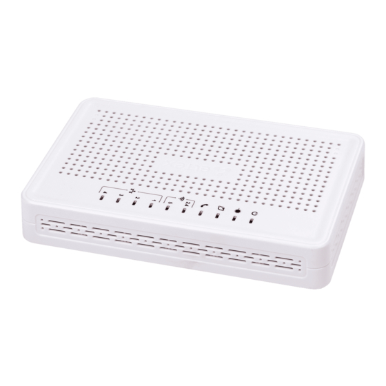
Figure 8 – NTU-RG-5402G-W, NTU-RG-5421G-Wac and NTU-RG-5421G-WZ side panel layout Table 6 for detailed information about buttons located on the side panel of the device. Table 6 – NTU-RG-5402G-W, NTU-RG-5421G-Wac and NTU-RG-5421G-WZ side panel buttons description Rear panel element Description... - Page 10 Figure 9 – NTU-RG-5402G-W (on the left) and NTU-RG-5421G-Wac, NTU-RG-5421G-WZ (on the right) top panel layout Current status of the device is represented by means of indicators paced on the top panel. Table 7 provides possible statuses of the LEDs.
- Page 11 flashes transmitting data via Wi-Fi Wi-Fi network is inactive 1..4 – Ethernet port activity indicator green established 10/100 Mbps connection orange established 1000 Mbps connection flashes transferring data packets The front panel of NTU-RG-5421GC-Wac is shown in Figure 10 Figure 10 – NTU-RG-5421GC-Wac front panel layout The LED indicators located on the front panel show the current state of the device.
- Page 12 indicator device startup is in progress green device startup completed, the current device configuration differs from the default one orange device startup is completed, the default configuration is set Figure 11 shows NTU-RG-5440G-Wac, NTU-RG-5440G-WZ top panel layout. Figure 11 – NTU-RG-5440G-Wac and NTU-RG-5440G-WZ top panel layout Current status of the device is represented by means of indicators paced on the top panel.
-
Page 13: Reboot And Reset To Factory Settings
Reboot and Reset to Factory Settings For device reboot, press the «Reset» button once on the device side panel for NTU-RG-5402G-W, NTU-RG-5421G-Wac and NTU-RG-5421G-WZ; the «F» button on the device rear panel for NTU-RG-5421G-Wac, NTU-RG-5440G-Wac, NTU-RG-5440G-WZ. In order to reset the device to the factory settings, press the «Reset» button and hold it for 7-10 seconds until the indicator glows red and all other LEDs go out. - Page 14 Figure 12 – Logical Architecture of a Device with Factory Settings Main Components of the Device: Optical receiver/transmitter (SFF module) for conversion of an optical signal into an electric one; Processor (PON chip) which converts Ethernet and GPON interfaces; Wi-Fi modulesfor wireless interfaces of the device. A device with factory (initial) settings have the following logical blocks (see Figure 12 Br0;...
- Page 15 When the device is successfully connected, username and password request page will be shown in the browser window: Enter your username into ‘User Name’ and password into ‘Password’ field. Username: user , password: user Click the ‘Login’ button. In the browser window, the home page of the device’s web interface will open. Password changing To prevent unauthorized access to device in the future, it is recommended to change password.
- Page 16 The user interface window can be divided into 3 parts: The navigation tree on the device settings menu. The main settings window for the selected section. User change button. The «Status» menu. Device Information The «Device status» submenu. Device General Information This section displays general information about the device, the main parameters of the LAN and WAN interfaces.
- Page 17 System Board Type – device model; Serial Number – device serial number; PON Serial – device serial number in the PON network; Base WAN MAC – device WAN MAC address; Hardware Version – hardware version; Uptime – device uptime; Date/Time –...
- Page 18 The «IPv6 Status» submenu. Information about IPv6 system The tab displays the current status of IPv6 system. Status IPv6 LAN Configuration IPv6 Address – IPv6 address; IPv6 Link-Local Address – local IPv6 address. Prefix Delegation Prefix – IPv6 address prefix. WAN Configuration Interface –...
- Page 19 PON Status Vendor Name – manufacturer name; Part Number – part number; Temperature – current temperature; Voltage – voltage; Tx Power – transmission power; Rx Power – reception power; Bias Current – bias current; Video Power – video signal power PON Status ONU State –...
- Page 20 The LAN Port Status table shows: LAN port number; port state (Up/Down); rate of external network device connection to the port (10/100/1000 Mbps). The «VoIP» submenu. Information on VoIP status In the «VoIP» section you can view the status of the VoIP network interface. Status VoIP Port –...
- Page 21 To save the changes, click the «Apply Changes» button. The «Wireless» menu. Wireless network configuration This section contains individual settings for each of the operating bands – 2.4 GHz (wlan0) and 5 GHz (wlan1). The «Status» submenu. Current WLAN status This submenu displays the current status of the WLAN.
- Page 22 Disable WLAN Interface – disable radio interface; Band – change Wi-Fi operation standard; Mode – switch the «AP/Client» operation mode; SSID (ServiceSet Identifier) – assign a wireless network name (case sensitive); Default device SSID is ELTX-2.4GHz_WiFi__aaaa/ELTX-5GHz_WiFi_aaaa, where – the last 4 digits of WAN MAC. WAN MAC is labelled on the device housing.
- Page 23 To save the changes, click the «Apply Changes» button. The «Show Active WLAN Client» button outputs the table of active WLAN clients. Wireless wlan0 (2.4GHz) / wlan1 (5GHz) Basic settings Show Active WLAN Client MAC Address – MAC address of the client; Tx Packets –...
- Page 24 Fragment Threshold – set the fragmentation threshold, in bytes. If a packet size exceeds the value, the packet is fragmented into parts of the corresponding size; RTS Threshold – if the packet is smaller than the RTS threshold value, the RTS/CTS mechanism (with request to send/clear to send packets) is not used;...
- Page 25 To save the changes, click the «Apply Changes» button. The «Security» Submenu. Security Settings Use this menu to configure general data encryption settings for a wireless network. The client wireless equipment can be configured either manually or automatically with the help of WPS. Wireless wlan0 (2.4GHz) / wlan1 (5GHz) Security SSID Type –...
- Page 26 RADIUS Server Password – Secret key for access to the RADIUS server; IEEE 802.11w – enable service frame encryption; None – disable service frame encryption; Capable – encryption compatibility mode; Required – encryption is required. SHA256 (Enable/Disable) – enable/disable SHA256 usage. WPA Cipher Suite –...
- Page 27 The table displays the following information: SSID – wireless access point name; BSSID – access point MAC address; Channel – channel; Type – type (AP (Access Point), Client); Encryption – encryption method; RSSI – received signal level. To scan the environment, click the «Refresh» button. The «WPS»...
- Page 28 DHCP Mode – select operation mode: NONE – DHCP disabled; DHCP Server – operation in DHCP server mode; DHCP Relay – operation in DHCP repeater mode. IP Pool Range – range of addresses distributed among clients; Show Client – button to view clients who leased the addresses. When clicking, a table with information about DHCP clients leased by a DHCP server is displayed;...
- Page 29 Enable – when selected, enable DHCP server (IP addresses from the following range will be dynamically assigned to network devices); D-DNS Provider – select the type of D-DNS service (provider): org TZO.com No-IP.com; Custom – another provider selected by user. In this case, you need to specify the provider's name ( Hostname ) and address ( Interface...
- Page 30 The «IP/Port Filtering» submenu. Address Filtering Settings This section is used to configure address filtering. The IP Filtering function filters router traffic by IP addresses and ports.Using these filters can be useful to protect or restrict the local network. Services Firewall IP/Port Filtering Default action Incoming Default Action Deny Allow –...
- Page 31 Default Action – default settings: Deny – when checked, traffic pass is prohibited by default; Allow – when checked, traffic pass is allowed by default; MAC Address – MAC address for which limitation/access should be imposed. «Current Filter Table» «Rule» «Allow»...
- Page 32 Port Forwarding (Enable/Disable) – enable/disable port forwarding feature; Application – this menu has pre-settings for various applications port forwarding; Comment – comment; Local IP – local IP address to which forwarding is performed; Local port from/to – specify the range of local device ports for forwarding; Protocol –...
- Page 33 To save the changes, click the «Apply Changes» button. All blocked domains are listed in the «Domain BlockingConfiguration» table, to remove a blocking for one domain, select it and click the «Delete Selected» button, to remove all restrictions, click the «Delete All» button. The «Port Triggering»...
- Page 34 The «RIP» submenu. Dynamic routing configuration This section is used to select the interfaces on your device is that use RIP, and the version of the protocol used. Enable the RIP if you are using this device as a RIP-enabled Device to communicate with others using the Routing Information Protocol. Services RIP RIP (Enable/Disable) –...
- Page 35 Username – account name ; New password – password; Confirmed Password – password confirmation . «Shares» section is used to add Samba library. Services Samba Shares Share name – library name; Path – path to library; Read only – read only; Write list –...
- Page 36 The «Bridging» submenu. Bridging parameters configuration In this section you can configure bridge parameters. Here you can configure aging time of addresses in MAC table as well as to enable/disable 802.1d Spanning Tree. Advance Bridging Ageing Time – address lifetime (s); 802.1d Spanning Tree (Enable/Disable) –...
- Page 37 To add the static route check «Enable» , fill the corresponding fields and click «Add Route». Enable – flag for route adding; Destination – destination address; Subnet Mask – subnet mask; Next Hop – next host; Metric – metric; Interface – interface. Added static routes are displayed in the «Static Route Table»...
- Page 38 In this submenu you can configure RADVD (Router Advertisement Daemon). Advance IPv6 RADVD MaxRtrAdvInterval – maximum RA (Router Advertisement) sending interval; MinRtrAdvInterval – minimum RA sending interval; AdvManagedFlag – enable/disable «Managed» flag sending in RA; AdvOtherFlag – enable/disable Other RA flag sending. To save the changes, click the «Apply Changes»...
- Page 39 To save the changes, click the «Apply Changes» button. After clicking on the «Show Client» button, a table of active DHCPv6 server IP addresses will be displayed. Advance IPv6 DHCPv6 Show Client The «MLD proxy» submenu. MLD proxy function configuration In this section you can enable/disable MLD-proxy operation.
- Page 40 Enable – flag for route adding; Destination – destination address; Next Hop – next host; Metric – metric; Interface – interface. «Static IPv6 Route Table» To add IPv6 Routing, fill in the appropriate fields and click the «Add Route» button: Added routes are displayed in the , to update the information click the «Update»...
- Page 41 Default Action – default action: Deny – when checked, traffic pass is prohibited by default; Allow – when checked, traffic pass is allowed by default; Protocol – select protocol; Source Interface ID – source interface; Destination Interface ID – destination interface; Source Port –...
- Page 42 To display the path of the information packet from its source to its destination, you should enter its IP address in the «Host Address» field, specify the number of transit sections and press the «Go» button. The «Admin» submenu Device management section. In this menu, you can configure passwords, time, configurations, etc. The «Settings»...
- Page 43 PLOAM Password – password to activate the terminal on OLT. To save the changes, click the «Apply Changes» button. It is not recommended to change the activation password without consulting your ISP. The «Commit/Reboot» submenu. Saving changes and rebooting the device Click the «Commit and Reboot»...
- Page 44 To change the password, you must enter the existing password in the «Old Password» field, then the new password in «New Password» and confirm it with «Confirmed Password» To confirm and save changes, click the «Apply changes» button. Click the «Reset» button to reset the value. The «Firmware upgrade»...
- Page 45 The «Time zone» submenu. System time configuration In this section you can configure the device system time. Synchronization with accurate online time-servers is available. Admin Time zone Current time – current time; Time Zone Select – timezone; Enable Daylight Saving Time – enable daylight saving time; Enable SNTP Client Update –...
- Page 46 Statistics PON Bytes Sent – transmitted bytes; Bytes Received – received bytes; Packets Sent – packets transmitted; Packets Received – packets received; Unicast Packet Sent – Unicast packets transmitted; Unicast Packet Received – Unicast packets received; Multicast Packets Sent – Multicast packets transmitted; Multicast Packets Received –...
- Page 47 The list of changes Document version Suitable firmware version Issue date Revisions Version 1.4 2.1.0 07.2020 Fifth issue Version 1.3 1.2.1 12.2019 Fourth issue Version 1.2 1.2.0 10.2019 Third issue Version 1.1 1.1.0 04.2019 Second issue Version 1.0 1.0.1 11.2018 First issue...
Need help?
Do you have a question about the NTU-RG-5402G-W and is the answer not in the manual?
Questions and answers