
Subscribe to Our Youtube Channel
Related Manuals for Fisher Scientific Isotemp 60L Incbtr Grvity 120V


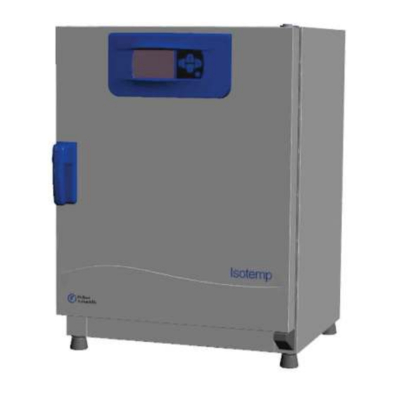
Summary of Contents for Fisher Scientific Isotemp 60L Incbtr Grvity 120V
- Page 2 This document is not part of any sales contract between Fisher Scientific and a purchaser. This document shall in no way govern or modify any Terms and Conditions of Sale, which Terms and Conditions of Sale shall govern all...
- Page 3 Basic Operating Precautions ....................... 1-1 Operational Safety Rules ........................1-2 Warranty ............................1-2 Explanation of Safety Information and Symbols ................. 1-3 Intended Purpose of the Incubator ..................... 1-6 Standards and Directives ........................1-6 Packaging ............................2-1 Acceptance Inspection ........................2-1 Scope of Supply..........................
- Page 4 Powering Up ............................7-5 Switching the Oven Off / Powering Down..................7-5 Temperature Set Value ........................7-6 Timer ..............................7-7 Settings............................... 7-9 Shutting the Incubator Down......................8-1 Cleaning............................. 9-1 Wipe / Spray Disinfection ........................9-1 Predisinfection............................ 9-3 Inspections and Checks ........................10-1 Service Intervals..........................
- Page 5 Figure 3-1 Table-top incubators, dimensions and required clearances ..............3-3 Figure 3-2 Lift Points............................. 3-4 Figure 4-1 Isotemp 60L/100L/180L Incbtr Grvity Front View................4-2 Figure 4-2 Isotemp 60L/100L/180L Incbtr Grvity Rear View ................4-3 Figure 4-3 Isotemp 60L/100L/180L Incbtr FA Front View ................... 4-5 Figure 4-4 Isotemp 60L/100L/180L Incbtr FA Rear View..................
- Page 7 These operating instructions describe Fisher Scientific incubators. Fisher Scientific incubators have been manufactured to the latest state of the art and have been tested thoroughly for flawless functioning prior to shipping. However, the incubator may present potential hazards, particularly if it is operated by inadequately trained personnel or if it is not used in accordance with the intended purpose.
- Page 8 The following rules must be heeded when working with Fisher Scientific incubators: • Observe the sample weight limits specified for your Fisher Scientific incubator as a whole and its shelving in particular; see Chapter 13, “Technical Data.” • Do not load the bottom of the interior workspace to avoid the risk of overheating any samples placed there and to prevent the temperature sensor from being damaged.
- Page 12 Fisher Scientific incubators are laboratory devices for preparing and cultivating cell and tissue cultures. The devices employ precision temperature control for simulating the specific physiological ambient conditions for these cultures. Fisher Scientific incubators are for professional use only. To avoid the risk of explosion do not load the incubator with tissue, material, or liquids that: •...
- Page 13 After the incubator has been delivered, check the delivery immediately for: • completeness, • possible damage. If components are missing or damage is found on the incubator or the packaging, in particular damage caused by humidity and/or water, please notify the carrier as well as Fisher Scientific Technical Support immediately.
- Page 14 Perforated shelves Support rail for shelf table-top incubators Shelf support Power cord Clip springs for table-top incubators Plug Anti-tilt anchor Operating manual...
- Page 15 The incubator must only be operated in a location that meets all of the ambient condition requirements listed below: • Installation location indoors in dry areas free from drafts. • The dust burden may not exceed the contamination category 2 based on EN 61010-1. Using the incubator in an atmosphere with electrically conductive dust is prohibited.
- Page 16 • Transient surges must lie within the range of levels that normally occur in the power supply system. The impulse withstand voltage based on surge category II of IEC 60364-4-443 shall be applied at the nominal voltage level. • Consider installing one dedicated upstream circuit breaker per incubator to avoid multiple device failures in case of an electrical fault.
- Page 17 Model A (mm/inch) B (mm/inch) C (mm/inch) D (mm/inch) * Depth of handle /display (66 mm/2.6 in) not included in overall depth specified; height of adjustable feet (36 mm/1.4 in) not included in overall height specified. E (mm/inch) F (mm/inch) G (mm/inch) H (mm/inch)
- Page 18 For transport, do not lift the incubator using the doors or components attached to the incubator as lift points.
- Page 19 Fix the anti-tilt anchor to a solid part of the building. Fisher Scientific floor stand incubators must always be attached to the wall using two (2) retaining brackets on the outer left and right side on the back of the unit.
- Page 20 Remove the screws. Attach the end of the retaining bracket that is facing downward to the unit. Align the device at roughly 90°, +/-20° to the retaining bracket. Affix the retaining bracket to the wall. Additionally, the following caution notes must be heeded at all times:...
- Page 21 This section describes Fisher Scientific microbiological incubators: • Fisher Scientific Gravity convection incubators: • Fisher Scientific Forced air incubators. This section describes the Fisher Scientific microbiological incubators for standard laboratory applications. Gravity convection incubators come equipped with the following features: •...
- Page 22 Outer door Door latch cutout Door latch and handle Door hinge, lower Levelling foot Nameplate Perforated shelf Support rail for perforated shelf Shelf support [10] Door hook catch [11] Door seal [12] Stacking pad [13] Glass door [14] Temperature sensor...
- Page 23 [3] Door bearing [4] Access port [5] Electronics compartment [6] Leveling foot...
- Page 24 Forced Air Incubators come equipped with the following features: • high-precision work space temperature control, adjustable in steps of one-tenth of a degree up to 75 °C (167 °F) • one speed work space fan • an on/off timer • two perforated shelves •...
- Page 25 The individual features of forced air incubators are shown in the figures below. Outer door Door latch cutout Door latch and handle Door hinge, lower Levelling foot Nameplate Temperature sensor Support rail for perforated shelf Shelf support [10] Fan opening, air baffle [11] Door hook catch [12] Air baffle [13] Door seal...
- Page 26 [3] Door bearing [4] Access port [5] Electronics compartment [6] Leveling foot The incubators are equipped with the following safety features: • a sample protection feature that safeguards the samples against destruction through overheating in case of controller failure; • dual fuses rated at 16 amperes. To ensure undisturbed operation, the ambient temperature in the operating room must be at least 18 °C (64.4 °F).
- Page 27 The PT 100-type sensor for the control of the work space temperature and for the thermal protection [1] is installed on the bottom of table-top incubators and in the top of floor stand incubators. The work space temperature sensor provides the inputs to the incubator’s built-in controller, which continuously compares the measured values to the user-specified set value and adjusts the heaters according to the result.
- Page 28 The RS- 232 interface (item 2 in figure 5 below) may be used to connect Fisher Scientific incubators to the serial interface port of a computer to allow for the computer-aided acquisition and documentation of major operating parameters (temperature, error codes, etc.).
- Page 29 All components of the work space are made of corrosion-resistant stainless steel and have an absolutely smooth and easy-to-clean surface. Any embossings have a large radius. A re-sealable, capped access port (can be closed off using the plugs delivered with the unit) allows cables, hoses or additional sensor leads to be routed into the work space of the incubator.
- Page 30 The incubator is supplied with two perforated shelves. The shelf support rails [1] have an alternating pattern of oblong and round perforations spaced evenly at 30 mm, allowing the shelf support brackets [8] to be inserted without any room for error, yet in a very flexible way to accommodate any required height of sample container.
- Page 31 Air Baffles Retaining Springs (only for table-top incubators) Support Rails Shelf Support Shelves...
- Page 33 The installation of the shelf system does not require any tools. The support rails are secured in place by spring action. Once the shelf support is inserted into the rails, the perforated shelves can be simply pushed onto their support hooks to complete the installation. 1.
- Page 34 The illustration below shows the placement of the shelf system elements. Clip spring Support rail (for floor stand units, air baffle) Shelf support Perforated shelf Air Baffles Retaining Springs (only for table-top incubators) Support Rails Shelf Support Shelves...
- Page 35 Upon delivery, Fisher Scientific incubators are not in a sterile state. Before the initial start-up, the incubator must be decontaminated. The following work space components should be checked for cleanliness and disinfected prior to use: • support rails (table-top units), •...
- Page 36 1. Place the support rail [4] on the lower embossing [6] and tilt it upwards against the work space side wall so that the rail is positioned over the two embossings at [5] and [2]. 2. Clamp the retaining spring [3] behind the upper embossing [1]. 3.
- Page 37 1. Push the shelf [4] onto the shelf support with the tilt protection devices [2] facing the rear panel of the incubator. 2. Slightly raise the perforated shelf so that the pull-out stops [1] and [3] can slide over the shelf support.
- Page 38 On the 85911-430 model loosen and remove the six (6) screws for the rear air baffle and bottom air baffles and then remove the air baffles. Check to ensure that the air baffles are securely screwed into place after cleaning and moving the unit.
- Page 39 5. Make sure the power cord is not subjected to tensile or compressive force. The alarm contact is not functional with gravity convection incubators. If you have a need for alarming, please contact Fisher Scientific Customer Support for advice.
- Page 40 The RS-232 data communication interface supports the querying of status information and temperature data from the incubator by entering basic commands in a standard terminal window provided by your computer’s operating system. The interconnection requires a standard RS-232 cable with 9-pin connectors and a straight “1:1” pinout without any crossed wires, which is not supplied with the incubator.
- Page 41 3. Connect one connector of the serial interface cable (cable length, 5 to max. 10 m, not supplied as a standard item) to the socket labeled RS 223 in the computer and alarm interface section at the rear of the incubator (see “not used”...
- Page 43 The incubator must not be released for operation before all major start-up activities have been completed (see chapter 5, “Start-up.” Prior to starting operation, the following incubator components must be checked for their correct function: • The door seal in the front frame must not be damaged. •...
- Page 45 Fisher Scientific incubators come with a front panel mounted control unit consisting of a multi-functional display, four control buttons, and an on/off button. The four control buttons interact with the display window to let users access all of the user control functions and adjustments of the incubator, including - for example, the temperature set value, timer, energizing/de-energizing, as well as a variety of other functions.
- Page 46 The table below contains brief descriptions of the buttons on the control panel figure...
- Page 47 If a menu item cannot be selected, then the function it represents is not part of the equipment configuration of your unit. The table below contains brief descriptions of the menu bar icons (item D2 in figure Left Right Menu/Enter...
- Page 49 1. Plug the power plug of the oven into a suitable protection-earthed AC power outlet. In the display window on the front panel the readiness indicator icon (top right item at D3 in figure page 7-1) is illuminated. 2. Keep the button depressed for two seconds.
- Page 50 Fisher Scientific incubators allow for setting the desired work space temperature directly using only a few button presses. After confirming the new temperature set value, you may trace the resulting temperature change in the temperature display field (item D1 in...
- Page 51 The Timer feature from the menu bar enables the user to set a “countdown-type” on or off timer that switches the incubator on or off after a preset period of time. Instructions for setting an off timer are given in table 7-5 (see below), while the usage of an on timer is described in table 7-6...
- Page 53 The Settings menu item opens a sub-menu populated with various commands for viewing general status information on the Fisher Scientific unit and setting for the operation of the incubator or its display window: • Read access to error log • Calibrating the incubator •...
- Page 54 Settings The Settings -> Calibration menu item enables the user to initiate a temperature calibration process (see “Temperature Calibration Procedure” page 10-3) for the built-in temperature sensors and choose whether calibration should be accomplished manually or automatically: • The Manual option allows for entering an absolute temperature directly, as measured - for example, using an external reference sensor.
- Page 55 The Settings ->°C / °F menu item allows for toggling the incubator used for displaying temperatures between degrees Centigrade and Fahrenheit. This setting does not have any impact on data logging via the RS-232 interface. Any temperature data that is logged to a computer for operational parameter documentation purposes is handed over in °C.
- Page 56 °C °F Settings...
- Page 57 This chapter provides instructions for shutting the incubator down for prolonged periods of time, that is, at least for several days in a row. 1. Remove the containers with the cultures, all accessories, and other objects from the work space. 2.
- Page 59 Remove dirt residues and depositions thoroughly using a solution of lukewarm water and commercial detergent. Wipe the surfaces clean using a clean cloth and clear water. Then, wipe the surfaces dry using a clean cloth. The manual wipe and spray disinfection is a three-stage process: •...
- Page 61 1. Remove all samples from the work space and store them in a safe place. 2. Spray disinfectant onto the surfaces of the work space and of the accessories or wipe the surfaces clean using disinfectant. 3. Allow time for the disinfectant to act as specified by the manufacturer. 1.
- Page 62 2. Let the disinfectant work on the surfaces/internals as detailed in the manufacturer’s instructions. 3. Re-install the internals in the specimen chamber.
- Page 63 Maintenance and inspection at regular intervals of the features and components listed below are mission-critical to maintain the product in a fully operative and safe condition and avoid malfunctions due to aging and wear. Failure to perform maintenance on a regular basis may result in: •...
- Page 64 During running operation, the following service works must be performed: • Perform the comparative temperature measurement outlined in the following section. • Have the incubator inspected and services by a Fisher Scientific authorized Technical Service agent. To determine the exact measured value of the incubator’s integral temperature sensor, a temperature comparison measurement must be performed every three months.
- Page 65 To minimize temperature variations during the measurement, put the measuring sensor in an isothermal container (such as a bowl filled with glycerol) before placing it in the work space. Use the center of the work space as the reference location for the comparison measurement. 1.
- Page 66 The door seal of the outer door is located in the retaining slot. The door seal should be inspected for any signs of embrittlement at half-yearly intervals. No tools are required to replace the seal. 1. Pull the seal out of the guide slot. 2.
- Page 67 Prior to returning any materials, please contact our Customer Service Department for a “Return Materials Authorization” number (RMA). Material returned without an RMA number will be refused.
- Page 71 table 12-1 below lists the error messages that may appear in the control panel display window (see “Error Log” page 7-9) and provides instructions for clearing such alarms.
- Page 73 Clearing should mute the audible alarm, de-energize the alarm relay, and clear the message from the control panel display.
- Page 75 The technical data are valid only for an empty device equipped with three shelves, a spray-painted outer enclosure and a power line voltage 120 V/60 Hz. Options may have an impact on the specified performance.
- Page 79 50126665 Stacking adapter 60L unit 50126666 Stacking adapter 100L unit 50126667 Stacking adapter 180L unit 50127105 Kit fresh air filter for Isotemp forced air incubators 50127146 Fresh air filter for Isotemp forced air incubators 50127431 Outer door for 60L units with a door stop on the left side 50127432 Outer door for 100L units with a door stop on the left side 50127433...
- Page 80 50127455 Outer door for 100L unit with a door stop on the right side 50127456 Outer door for 180L with a door stop on the right side 50140962 Kit electronic insert for Isotemp incubators and heating & drying ovens without main board fan 50140965 Kit electronic insert Isotemp incubators and heating &...
- Page 81 50127762 Wire mesh shelf for 100L gravity units, including 2 shelf supports 50127763 Wire mesh shelf for 180L gravity units, including 2 shelf supports 50127764 Wire mesh shelf for 60L forced air units, including 2 shelf supports 50127765 Wire mesh shelf for 100L forced air units, including 2 shelf supports 50127766 Wire mesh shelf for 180L forced air units, including 2 shelf supports 50127770...
- Page 82 50128792 Drip tray for 180L incubators 50128793 Petri dish holder 50 mm (2 inch) for 60L incubators 50128794 Petri dish holder 50 mm (2 inch) for 100L incubators 50128815 Petri dish holder 50 mm (2 inch) for 180L incubators 50128816 Petri dish holder 90 mm (2 inch) for 60L incubators 50128818 Petri dish holder 90 mm (2 inch) for 100L incubators...
- Page 85 Fisher Scientific Company L.L.C 275 Aiken Road Asheville, NC 28804 United States © 2018 Fisher Scientific Inc. All rights reserved. Trademarks used are owned as indicated at www.fishersci.com/trademarks. In the United States: For customer service, call 1-800-766-7000 To fax an order, use 1-800-926-1166...
Need help?
Do you have a question about the Isotemp 60L Incbtr Grvity 120V and is the answer not in the manual?
Questions and answers