Table of Contents
Advertisement
Quick Links
Sherwood Scientific Ltd
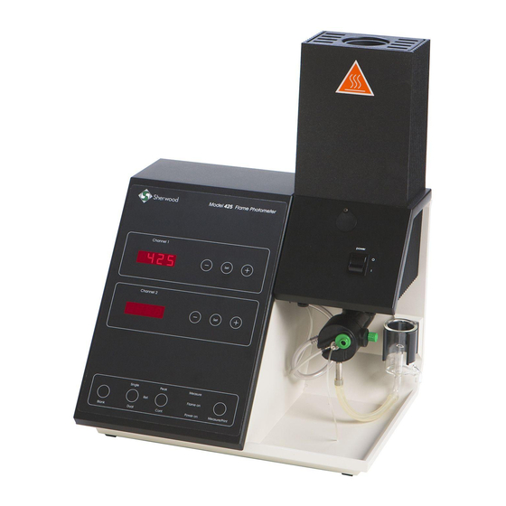
Model 420 & 425 Flame Photometer
Service Manual
Sherwood Scientific Ltd.
1 The Paddocks
Cherry Hinton Road
Cambridge
CB1 8DH
England
Tel. +44 (0)1223 243444
Fax. +44 (0)1223 243300
e-mail: info@sherwood-scientific.com
http://www.sherwood-scientific.com
rd
425 89 001
Issue 6
23
March 2012
ECN 736
G:\DOCUMENT CONTROL\Manuals\Flame\425\42589001 M420 & M425 Service Manual Issue 6.doc
Advertisement
Table of Contents

Related Manuals for Sherwood Scientific 420

Summary of Contents for Sherwood Scientific 420
- Page 1 Sherwood Scientific Ltd Model 420 & 425 Flame Photometer Service Manual Sherwood Scientific Ltd. 1 The Paddocks Cherry Hinton Road Cambridge CB1 8DH England Tel. +44 (0)1223 243444 Fax. +44 (0)1223 243300 e-mail: info@sherwood-scientific.com http://www.sherwood-scientific.com 425 89 001 Issue 6...
-
Page 2: Table Of Contents
Model 420 & 425 Flame Photometer Contents Introduction Introduction ........... 5 Intended Use ........... 5 Positioning and Services Electrical Supply ........... 6 Fuel ..............6 ..............6 Waste Container ........... 6 Site Conditions ........... 6 Performance Characteristics and Specifications Specification ........... - Page 3 Model 420 & 425 Flame Photometer Contents Rear Panel Controls and Connections ... 10 Channel 1 & 2 Data Outputs ………………. 10 RS232/Printer Output ........10 External Device Output ........10 Power ..............10 ..............11 ..............11 Air Regulator .............
- Page 4 Model 420 & 425 Flame Photometer Contents Exploded Views General Arrangement, upto s/n 20410 .... 20 EV1a General Arrangement, s/n 20411 on ……… 21 Front Panel Assembly ........23 Main Chassis Assembly ........25 Gas Chassis Assembly ........27, 28 Rear Mounted Components ......
-
Page 5: Introduction
The Model 420 & 425 can also function as a single channel instrument for the determination of Li samples as well as Na or K or Ca (M425 only). -
Page 6: Positioning And Services
The instrument must be places on a strong, level worktop free from vibration. The Model 420 & 425 require approximately 500mm x 500mm of bench space, which includes an area in front for solutions and clearance at the rear for tubing. -
Page 7: Performance Characteristics And Specifications
Model 420 & 425 Flame Photometer Performance Characteristics and Specifications Specification For specification refer to Operators Manual Section 4.1, 4.2, 4.3 & 4.4. Warm Up To achieve the stated specification the flame must be alight for a minimum of 15 minutes, with diluent being aspirated. -
Page 8: Front Panel Controls And Indicators
Model 420 & 425 Flame Photometer Front Panel Controls and Indicators Controls ‘-’ ‘Set’ ‘+’ Primarily used in the Calibration process. Secondary functions include date and time, and filter factor setting. ‘Blank’ Forces the instrument to zero all channels. Must be used at start-up and after a change of Peak/Cont., Single/Dual or Element selection. -
Page 9: Print
Model 420 & 425 Flame Photometer Front Panel Controls and Indicators continued ‘Print’ Used to cause an output to RS232 serial port (connected to a printer, computer or data logger). Operates the same in both ‘Cont.’ and ‘Peak’. Sample must be introduced before ‘Print’ is pressed. -
Page 10: Cont
9 pin standard RS232 ‘D’ connector, for serial printers and data logging devices. External Device Output This is a 6 pin miniDIN connector which enables the Model 420 & 425 to be connected to the Model 860 Autosampler. -
Page 11: Gas
Rear Panel Controls and Connectors continued ¼ inch fuel inlet connector, permanently connected to the regulator inlet. The Model 420 & 425 will operate satisfactorily on Propane and Butane. All fuels to be free of heavy hydrocarbon deposits and regulated at the cylinder to a pressure of 2.1 kg/cm² (30psig). -
Page 12: Cleaning And Maintenance Procedures
Cleaning & Maintenance Procedures Cleaning & Maintenance Procedures The Model 420 & 425 have been designed to allow customers to carry out all routine maintenance procedures, e.g. Daily, Weekly, Monthly and Six Monthly. Refer to the Operators Manual for detailed information. -
Page 13: Instrument Description
Model 420 & 425 Flame Photometer Instrument Description General This section describes the electrical and electronic circuits. The following PCB’s are fitted. Title Part number Fitted to Main PCB 425 65 001 Serial number 15542 onwards Rear PCB 425 65 002 Serial number 15542 onwards Except for the ‘power’... -
Page 14: Replacement Procedures
Model 420 & 425 Flame Photometer Replacement Procedures Printed Circuit Board Remove the front panel, by unscrewing the six screws securing it in place. Two on the bottom front edge and four along the top back edge (two of which are recessed). -
Page 15: Air Pressure Switch
Model 420 & 425 Flame Photometer Replacement Procedures continued Air Pressure Switch Follow steps 1 & 2 of the above procedure to remove the front panel. Pull back, or cut away sleeving and de-solder the two wires, making a note of there positions. -
Page 16: Photocell
Model 420 & 425 Flame Photometer Replacement Procedures continued Photocell Follow steps 1 & 2 of the above procedure to remove the front panel. Remove the 12 way connector PL1(Sensors) from the PCB. All four photocells connect to this plug,, establish which is to be replaced. -
Page 17: Filter Factors
Filter Factor The new filters will have new ‘Factors’, which must be programmed into the Model 420 & 425. Press and hold down the channel 2 ‘Set’, ‘Blank’ & ‘Print’ buttons until the unit beeps. The top display will show a number and the lower display ‘F1’. -
Page 18: Spares
Model 420 & 425 Flame Photometer Spares Ordering Information The following information will be required when ordering spares: - Unit serial number Catalogue number of part Quantity required. 425 89 001 Issue 6 March 2012 ECN 736... -
Page 19: Ev1 General Arrangement
Model 420 & 425 Flame Photometer Spares Item No. Catalogue No. Description Quantity 425 54 001 Photocell Assembly 410 04 006 Inner Glass Chimney 420 08 102 Nebuliser 410 04 010 Constant Head and Drain (glass) 1 upto s/n 20410... - Page 20 Model 420 & 425 Flame Photometer Spares General Assembly - EV1 Upto s/n 40210 425 89 001 Issue 6 March 2012 ECN 736...
- Page 21 Model 420 & 425 Flame Photometer Spares General Assembly - EV1a From s/n 20411 425 89 001 Issue 6 March 2012 ECN 736...
-
Page 22: Ev2 Front Panel Assembly
Model 420 & 425 Flame Photometer Spares Item No. Catalogue No. Description Quantity 420 20 001 Ignitor unit assembly 425 65 001 Main PCB assembly Model 425 001 49 687 7 segment LED display, pack of 4 1 pack 425 89 001... - Page 23 Model 420 & 425 Flame Photometer Spares Front Panel Assembly - 425 89 001 Issue 6 March 2012 ECN 736...
-
Page 24: Ev3 Main Chassis Assembly
Model 420 & 425 Flame Photometer Spares Item No. Catalogue No. Description Quantity 410 08 005 Ignition electrode 410 15 001 Phototransistor assembly (flame sensor) 460 39 009 Burner 410 26 001 Mixing chamber and burner assembly 410 08 001... - Page 25 Model 420 & 425 Flame Photometer Spares Main Chassis Assembly - 425 89 001 Issue 6 March 2012 ECN 736...
-
Page 26: Ev4 Gas Chassis Assembly
Model 420 & 425 Flame Photometer Spares Item No. Catalogue No. Description Quantity 410 06 009 Air pressure gauge & regulator assembly upto s/n 23159 410 08 003 Air pressure gauge & regulator assembly 1 from s/n 23460 001 38 010 Solenoid valve Ø1.0mm orifice (RH) - Page 27 Model 420 & 425 Flame Photometer Spares Gas Chassis Assembly - Up to serial number 23159 425 89 001 Issue 6 March 2012 ECN 736...
- Page 28 Model 420 & 425 Flame Photometer Spares Gas Chassis Assembly - EV4a Serial number 23160 onwards 425 89 001 Issue 6 March 2012 ECN 736...
-
Page 29: Ev5 Rear Mounted Components
Model 420 & 425 Flame Photometer Spares Item No. Catalogue No. Description Quantity 001 08 435 Propane regulator 001 08 234 Propane regulator - primary 001 08 732 Butane regulator (for Camping Gaz) 001 08 733 Butane regulator (for 7.5 Kg cylinders) - Page 30 Model 420 & 425 Flame Photometer Spares Rear Mounted Components - EV5 425 89 001 Issue 6 March 2012 ECN 736...
- Page 31 Model 420 & 425 Flame Photometer Spares Piping Diagram 425 89 001 Issue 6 March 2012 ECN 736...
- Page 32 Model 420 & 425 Flame Photometer Spares Wiring Schematic For Instruments upto Serial Number 16445 425 89 001 Issue 6 March 2012 ECN 736...
- Page 33 Model 420 & 425 Flame Photometer Spares Wiring Schematic For instruments from serial number 16446 425 89 001 Issue 6 March 2012 ECN 736...
- Page 34 Model 420 & 425 Flame Photometer Rear Panel details 425 89 001 Issue 6 March 2012 ECN 736...
Need help?
Do you have a question about the 420 and is the answer not in the manual?
Questions and answers