
Related Manuals for Interpack IPG UA 262024 SB


Summary of Contents for Interpack IPG UA 262024 SB
- Page 1 UA 262024 SB CARTON SEALER UM095TW/UM595TW For All Other Serial Numbers, Please Contact Customer Service @ 800-474-8273 (Menu #3)
-
Page 2: Table Of Contents
ABLE OF ONTENTS Section 1 Table Of Contents------------------------------------------------------- 2 Section 2 Revision Control--------------------------------------------------------- 3 Section 2 Technical and Field Assistance------------------------------------ 4-5 Section 3 Warranty-------------------------------------------------------------------- 6 Section 4 Description of the UA262024 CARTON SEALER------------- 7-9 Section 5 Important Safeguards-------------------------------------------------- 10-17 Section 6 Specifications------------------------------------------------------------ 18-21 Section 7 Set-Up Procedures----------------------------------------------------- 22-31 Section 8 Operating Instructions------------------------------------------------ 32-35 Section 8 Troubleshooting--------------------------------------------------------- 36... -
Page 3: Section 2 Revision Control
EVISION ONTROL REVISION CONTROL REV00 Initial Release REV01 Second Release REV02 Third Release UA262024 SB Manual UM095TW / UM595TW UDM10008 UDM780-04... -
Page 4: Section 2 Technical And Field Assistance
SSISTANCE Technical Support This is the Interpack Model UA262024 SB Carton Sealer you ordered. It has been set up and tested in our factory with Intertape manufactured water activated tapes. If any problems occur when setting up or operating this equipment, please contact the authorized distributor from where you purchased this item. - Page 5 Troubleshooting section of this manual. Service support is available from your Authorized Interpack Distributor at additional cost if the problem cannot be remedied after consulting the Troubleshooting section of this manual.
-
Page 6: Section 3 Warranty
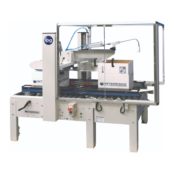
Intertape sells its Interpack Tape Heads, Case Tapers and Case Erectors with the following warranties: 1. The HSD ... - Page 7 UA262024 CARTON SEALER ESCRIPTION OF The UA262024 machine (figure1) is designed to fold and tape carton tops. It is easy to set-up and to operate. It can be adjusted to a wide range of carton sizes. Kicker Floating Tape Head Box Compression Guides Control Box Bridge...
-
Page 8: Section 4 Description Of The Ua262024 Carton Sealer
UA262024 CARTON SEALER ESCRIPTION OF How the UA262024 Works – Figures 2 & 3 When a new carton (item 1) reaches the Carton Sealer Machine rollers, it is pick-up by the Drive Sections (belts) (items 2) and carried forward into the machine. The sensor (item 3) detects carton which lowers the gate (item 4) to lets carton through. - Page 9 UA262024 CARTON SEALER ESCRIPTION OF Figure 3 UA262024 SB Manual UM095TW / UM595TW UDM10008 UDM780-04...
-
Page 10: Section 5 Important Safeguards
Important Safeguards There are a number of safety labels used on Interpack Carton Sealers. These labels are placed at different locations (refer to Figure 2) on the machine to warn operators and service personnel of possible dangers. Please read the labels on the machine and the following safety precautions before using the machine. - Page 11 Important Safeguards Safety decal location – Figure 5 The figure below shows where the safety decals are located on the machine. Replace any absent or illegible decal. Replacement decals can be found in the Parts section of this manual. W W ARNING ARNING OPERATION / SERVICE Only trained people are...
- Page 12 Important Safeguards There Are A Number Of Safety Labels Used On Intertape Case Sealers. The label shown is affixed to the upper tape head assembly on either side of the machine. It warns operators and service personnel of the presence of the cutting blade that may not be visible.
- Page 13 Important Safeguards The illustrated label shown is located on the “infeed and exit” ends of the machine belt drives. The label warns the operators and service personnel of the pinch point at each end of the belt drives. This label advises personnel about the dangers of the machine due to compressed air used in the system.
- Page 14 Important Safeguards The illustrated label shown is located on the side of the column. This label provides convenient safety instructions for the operator and service personnel in the operation of the Intertape Case Sealing Equipment. Note: Should any of the safety labels placed on the machine be damaged or destroyed, replacements are available.
- Page 15 Important Safeguards Explanation of Signal Word Consequences Warning: Indicates A Potentially Hazardous Situation, Which If Not Avoided Could Result In Death Or Serious Injury Or Property Damage Caution: Indicates A Potentially Hazardous Situation, Which If Not Avoided Could Result In Minor Or Moderate Injury Or Property Damage Warning •...
- Page 16 Important Safeguards Warning • To Reduce The Risk Associated With Mechanical, Pneumatic, and Electrical Hazards: a. Allow Only Properly Trained And Qualified Personnel To Operate And Service This Equipment. Operator Skill Level Descriptions Skill “A”: Machine Operator This Operator Is Trained To Use The Machine With The Machine Controls, To Feed Cases Into The Machine, Make Adjustment For Different Case Sizes, To Change The Tape And To Start, Stop, And To Re-Start Production Important: The Area Supervisor Must Ensure That The Operator Has Been...
- Page 17 Important Safeguards Operators Skill Level Required To Perform The Following Tasks On The Machine Operator Skill Number Of Operation Machine Condition Level Operators Running With Safety Protections Machine Installation & Set Up B & C Disabled Stopped By Pressing The Tape Roll Replacement Emergency Stop Button Blade Replacement...
-
Page 18: Section 6 Specifications
PECIFICATIONS UA262024 SB Carton Sealer Machine Dimensions Figure 6 Machine Dimensions Machine Weight: 701 lbs. (318 kg ) crated UA262024 SB Manual UM095TW / UM595TW UDM10008 UDM780-04... - Page 19 PECIFICATIONS 1. Operating Conditions Use in a dry, relatively clean environment at 40° to 105° F (5° to 40° C) with clean dry cartons. Machine must be set on a level surface or adjusted to operate on a level plane. 2.
- Page 20 PECIFICATIONS 4. Tape Specifications Use Intertape Brand Pressure Sensitive Carton Sealing Tape. The machine can accommodate 2” (48mm) to 3” (75mm) wide tape. A maximum tape roll diameter of 16 inches (405 mm) on a 3-inch (76.2 mm) diameter core can be installed on the tape head.
- Page 21 PECIFICATIONS 5. Carton Specifications Type • Regular Slotted Containers (RSC) • Other Style Cases May Be Processed. Consult Factory For Details. Material 125 To 275 PSI Bursting Test, Single Or Double Wall B Or C Flutes. Weight 85 lbs. Maximum (39 kg Max.) Size •...
-
Page 22: Section 7 Set-Up Procedures
ROCEDURES 1. Receiving and Handling The machine is shipped to the customer fixed to a pallet. The machine is enclosed with either a corrugated sleeve and cap or an HSC corrugated box. The sequence below is step by step instructions to remove all packing materials. Remove the strapping securing the corrugated sleeve and cap or HSC corrugated box to the •... - Page 23 ROCEDURES 2. Machine Height Adjustment Follow this procedure to adjust the height of machine: • Make sure machine is installed on near level ground • Use adjustable legs (figure 8) to adjust machine height and level. Machine height should be adjusted to incoming conveyor height. To adjust leg height: A.
- Page 24 ROCEDURES AIR PRESSURE ADJUSTMENT KNOB AIR FILTER 60 PSI AIR SUPPLY 4.1 BAR Figure 9 Pneumatic connection Height and Width Adjustment The UA262024 is designed to handle a full range of carton sizes. Follow theses procedures to set-up the machine to the proper carton length and width. Height adjustment: Press the emergency stop button (figure 4) to shut-off machine.
- Page 25 ROCEDURES Note: The purpose of the floating head is to absorb the pressure caused by over-filled cartons. F. Lower the bridge manually until it is well rested against the carton, without squeezing it down. G. Lock the bridge using the bridge lock lever (figure 10). Make sure to hold the bridge down while locking it.
- Page 26 ROCEDURES LOWER TO REST AGAINST CARTON TOP FLOATING MECHANISM LOCK HANDLE Figure 11 Width adjustment: Press the emergency stop button (figure 4) to shut-off machine. Use the width adjustment handle to spread the drive sections, enough to clear a carton. Set a carton on the machine, as shown in figure 12.
- Page 27 ROCEDURES DRIVE SECTIONS LIGHTLY SQUEEZE CARTON DRIVE SECTIONS USE HANDLE TO ADJUST BELTS LATERALLY Figure 12 Width adjustment NOTE: When width and length adjustments are completed, pull up emergency stop button to turn machine back on. Compression Guides Adjustment (figure 13) Compression guides (figure 13) must be adjusted to lightly squeeze the upper part of the carton.
- Page 28 ROCEDURES LOOSEN HANDLE TO ADJUST GUIDE GUIDES LIGHTLY SQUEEZE CARTON Figure 13 PULL AND TURN Figure 14 UA262024 SB Manual UM095TW / UM595TW UDM10008 UDM780-04...
- Page 29 ROCEDURES Kicker Adjustment (Figures 15 & 16) Kicker must be adjusted so that rear minor flap is folded correctly. The kicker must be adjusted according to the flap length. The kicker is factory adjusted to work with an average size carton. If you are operating with longer flaps (20”...
- Page 30 ROCEDURES Figure 16 7 Plow Rod Adjustment The plow rods are used for folding the major flaps. As the carton passes through the machine, the plow rods apply pressure to both flaps. The rods should be adjusted to obtain 90 degrees between each other, as shown in figure 17.
- Page 31 ROCEDURES Figure 18 Ski adjustment UA262024 SB Manual UM095TW / UM595TW UDM10008 UDM780-04...
-
Page 32: Section 8 Operating Instructions
PERATING NSTRUCTIONS For safe operation of the UA262024, you must be a qualified and authorized WARNING! operator. To be qualified, you must read and understand the written instruction supplied in the Operator’s manual and know the safety rules and regulations for the job. NOTE: Use only new cartons on this machine. - Page 33 PERATING NSTRUCTIONS forward and the kicker which folds the rear flap. You do not need to adjust these limit switches and it is strongly recommended NEVER to adjust the PC controller. Figure 20 Limit Switches UA262024 SB Manual UM095TW / UM595TW UDM10008 UDM780-04...
- Page 34 PERATING NSTRUCTIONS The UA262024 is a pneumatic machine and requires minimum maintenance. Bearings and cylinders are sealed and require no lubrication. The only maintenance required is listed below. • Regularly clean the machine using pressured air to remove carton dust from the moving parts.
- Page 35 PERATING NSTRUCTIONS Figure 22 Install new belt UA262024 SB Manual UM095TW / UM595TW UDM10008 UDM780-04...
-
Page 36: Section 8 Troubleshooting
ROUBLESHOOTING PROBLEM POSSIBLE CAUSE AND SOLUTION No air in system. Make sure air connection is made and air pressure is sufficient Nothing happens when carton reaches infeed Emergency stop button pressed down. conveyor Pull up button. Belts are not adjusted to squeeze box Conveyor belts are working but carton is not sufficiently. -
Page 37: Section 9 Replacement Parts
Trouble Shooting section of this manual. Service support is available from your Authorized Interpack Distributor at additional cost if the problem cannot be remedied after consulting the Trouble Shooting section of this manual. -
Page 38: Section 10 Optional Equipment
PTIONAL QUIPMENT Model Number Description Item Quantity Number Machine Feed/Exit Table 16” (.4 M) UM894T 1 or 2 Feed/Exit Table 24” (.6 M) UM998T 1 or 2 Feed/Exit Table 36” (.9 M) UM898T 1 or 2 Heavy Duty Casters, set of 6 UM708 1 set of 6 Secondary E-Stop... -
Page 39: Section 11 Appendix
– I PPENDIX LLUSTRATIONS AND ARTS ISTS Machine and Assemblies A-1 through A-53 See next page for beginning of illustration and parts. UA262024 SB Manual UM095TW / UM595TW UDM10008 UDM780-04... - Page 40 BASE ASSEMBLY (USM6104)
- Page 41 BASE ASSEMBLY (USM6104) ITEM NO. PART NUMBER DESCRIPTION QTY. UAM0352 BASE SUB-ASS'Y UPM4154EV INFEED TABLE UAM0275 LEG ASSEMBLY METRIC USM6111 DRIVE CENTRING ASS'Y UPM4173 PVC ROL CHARCOAL DIA 1.9 X 31.04 USM6110 GATE SA BOSCH GUIDED CYLINDER UAM1084 STOP START ELECTR. BOX USM0808 ELECTRIC ASSEMBLY UPM4402EV...
- Page 42 BASE SUB-ASSEMBLY (UAM0352)
- Page 43 BASE SUB-ASSEMBLY (UAM0352) ITEM NO. PART NUMBER DESCRIPTION QTY. UPM3287EV OUTSIDE FRAME UPM2522EV TRANSVERSE BRACING UPM3553 NEAR GAP FILLER UA2000 UPM3234EV OUTLET ROLLER BLOCK UPM3551EV OUTLET COVER UPM0609EV SLIDING PAD L.H. UPM0606EV SLIDING PAD R.H. UPM3235 ET T. H. INSERT 2" (OPTION) UPM3229 INLET COVER UF3713...
- Page 44 BASE ASSEMBLY (USM6104) MECHANISM...
- Page 45 BASE ASSEMBLY (USM6104) MECHANISM ITEM PART # DESCRIPTION QTY. UF1700 FW 1/4 ZINC UPM3242EV DRIVE SUPPORT SPACER UPM0576 BUMPER UF2231 SHAFT COLLAR W/SET SC-3/4" BORE UPM0631EV CHAIN TENSIONNER , BASE PLATE UPM0640EV CHAIN TENSIONNER , PIN UF6371 L.W. M10 UF3680 REG F.W.
- Page 46 LEG ASSEMBLY (UAM0275)
- Page 47 LEG ASSEMBLY (UAM0275) ITEM PART # DESCRIPTION QTY. UPM7640 LEG WELDMENT UPM7641 LEG ADJUSTMENT UPM7642 LEG FRICTION PLATE UF4231 FW M12 UF4230 L.W. ZINC M12 UF6393 HHCS M12-1.75 x 35 UF6392 CARRIAGE BOLT M10-1.5 x 25 UF3680 FW M10 UF6371 L.W.
- Page 48 GATE ASSEMBLY (USM6110)
- Page 49 GATE ASSEMBLY USM6110 ITEM NO. PART NUMBER DESCRIPTION QTY. UPM3804 GPC GUIDE CYLINDER 32mm X 50mm UPM3854 GATE FOR BOSCH GUIDED CYL UPM3787 FLOW CONTROL VALVE G 1/8 male 8mm tube UPM3870EV SPACER 20mm OD X 8.5mm ID X 57.1mm LG UF1190 FHCS M8 - 1.25 x 20 UF1821...
- Page 50 DRIVE SECTION RIGHT SIDE USM6102 A-11...
- Page 51 DRIVE SECTION RIGHT SIDE (USM6102) ITEM PART # DESCRIPTION QTY. UPM3544 BELT ENDL. SAG 12E, 50mm X 3156mm UPM3545EV, _3546EV DRIVE BASE RIGHT SIDE/ LEFT SIDE UPM3547EV, _3548EV DRIVE BASE COVER RIGHT SIDE / LEFT SIDE UPM0129EV DRIVE PULLEY UPM0259EV IDLER PULLEY UPM1879 TENSIONNER SLIDE...
- Page 52 USM6301 15 28 35 34 25 A-13...
- Page 53 USM6301 ITEM PART # DESCRIPTION QTY. ITEM PART # DESCRIPTION QTY. UPM3546EV DRIVE SECTION LH UPM3248EV SENSOR SUPPORT UPM3548EV DRIVE COVER LH UF5404 FHCS M5 - 0.8 x 16 mm UPM3544 BELT ENDL. SAG 12E, 2" X 124.5" UF1827 FW M5 UPM4450 DRIVE PULLEY UF7023...
- Page 54 USM6100 A-15...
- Page 55 USM6100 ITEM NO. PART NUMBER DESCRIPTION QTY. UPM4428EV COLUMN LH UPM0741EV COLUMN CAP LEFT SIDE UPM0737EV COLUMN BLOCK LEFT SIDE UPM0738EV COLUMN SHAFT UPM0742 SPRING SPOOL UPM0743 SPRING MANDREL SHAFT UPM3730EV SPRING ANCHOR LEFT SIDE UPM2251 SAFETY BUMPER UF5400 FHCS M5-0.8 x 12 mm UF1157 FHCS M5-0.8 x 70 UF3680...
- Page 56 USM6101 A-17...
- Page 57 USM6101 ITEM PART # DESCRIPTION QTY. UPM4429EV COLUMN RH UPM2182EV COLUMN CAP RIGHT SIDE UPM0735EV COLUMN BLOCK, RIGHT UPM4986 LINEAR BEARING 25 mm UPM0738EV COLUMN SHAFT UPM0742 SPRING SPOOL UPM0743 SPRING MANDREL SHAFT UPM2181 CONSTANT FORCE SPRING UPM3731EV SPRING ANCHOR RIGHT SIDE UPM2251 SAFETY BUMPER UF5400...
- Page 58 FLOATING TAPE HEAD BOX ASSEMBLY (USM6105) 32 33 34 A-19...
- Page 59 FLOATING TAPE HEAD BOX ASSEMBLY (USM6105) ITEM NO. PART NUMBER DESCRIPTION QTY. UPM3550EV T.H.BOX UPM1783EV PIVOT PLATE FRONT UPH0089EV BEARING PERMAGLIDE D1210 UPM0968EV PIVOT SHAFT T.H. BOX 222 UF6300 12mm RETAINING RING UF1250EV BHCS M6-1.0 X 16 UF1192 FHCS HK M6-1.0 X 16 UPM1158 PIVOT SHAFT SPACER UF1940...
- Page 60 LOCKING MECANSM (USM0391) A-21...
- Page 61 LOCKING MECANSM (USM0391) ITEM PART # DESCRIPTION QTY. UPM2187 SQUARE BAR 0.50" UPM0700 SINGLE LOCKING BLOCK UPM0698 FLANGED SCREW 1/2-13 L.H. UPM0699 FLANGED SCREW 1/2-13 R.H. UPM0703 SHORT BOX 3/4", 1/2" DR, 12 PT UPM0688 SINGLE LOCKING HANDLE UPM2184 SPRING, C1100-065-4000-M UF1318 BHCS M8-1.25 x 20 mm A-22...
- Page 62 COMPRESSION GUIDE (USM6109) A-23...
- Page 63 COMPRESSION GUIDE (USM6109) ITEM PART # DESCRIPTION QTY. UAM0288 KNOB CW 5mm PIN USA2324 UPM7538 GUIDE BLOCK TOP UF4029 FHCS HK M6-1 X 50 UPM2173EV WHEEL SUPPORT PLATE UA METRIC UPM3285EV GUIDE BLOCK UPM1659 WHEEL 2-7/8"DIA.COMPR.GUIDE UF0240 HHCS 3/8-16 x 1.75 A-24...
- Page 64 KNOB CW 5mm PIN (UAM0288) A-25...
- Page 65 KNOB CW 5mm PIN (UAM0288) ITEM PART # DESCRIPTION UPM4506 Knob w 3/8-16unc Hole UF9168 Internal Tooth LW 3/8" UF1540 HNR 3/8-16 UF2136EV Rod Zc 3/8-16 x 2" W/5mm Hole UPM0131EV Brass Pin 5mm A-26...
- Page 66 USM7077 14 3 2 13 33 18 A-27...
- Page 67 USM7077 ITEM NO. PART NUMBER DESCRIPTION QTY. UPM6118 SS BRIDGE EXTENSION UPM3849 SS CLEVIS PIN 0.50 DIA UF3552 SS 1/2" RETAINING RING UPM2900 BEARING BLK FOR 40mmCYL. UPM2901 REAR CLEVIS, 40mmCYL. UPM2917 CYLINDER ANCHOR BLOCK UPM2899 AIR CYL. 40 X 130mm ISO UPM6105 SS PIVOT PIN-SNAP RING UPM3874EV...
- Page 68 KICKER ASSEMBLY (USM6107) A-29...
- Page 69 KICKER ASSEMBLY (USM6107) ITEM NO. PART NUMBER DESCRIPTION QTY. UPM0380EV KICKER CLEVIS UPM3849EV SS CLEVIS PIN 12mm UF7017 SS 12MM RETAINING RING UPM2900 BEARING BLK FOR 40mmCYL. UPM2901 REAR CLEVIS, 40mmCYL. UPM2917EV CYLINDER ANCHOR BLOCK UF0835 SHCS M6-1 X 20MM UPM2899 AIR CYL.
- Page 70 RIGHT GUARD ASSEMBLY (USM6108) SEE DETAIL A SEE DETAIL B A-31...
- Page 71 RIGHT GUARD ASSEMBLY (USM6108) DETAIL A CORNERS MOUNTING ARRANGEMENT DETAIL B INSIDE CORNERS MOUNTING ARRANGEMENT A-32...
- Page 72 RIGHT GUARD ASSEMBLY (USM6108) ITEM PART # DESCRIPTION QTY. UPM3862EV LEXAN 6mm X 955mm X 1180mm UPM3864EV VERTICAL EXTRUSION UPM3865EV HORIZONTAL EXTRUSION UPM0614EV CORNER BLOCK UPM2922EV CORNER CAP FINISHING UF1250EV BHCS M6-1 x 16 mm UPM3852EV DOOR SUPPORT MEMBER UA2024 METRIC UPM3853EV DOOR SUPPORT UA 2024 METRIC UPM0732EV...
- Page 73 OPENED DOOR ASSEMBLY (USM6108) 11 10 12 33 27 A-34...
- Page 74 OPENED DOORS ASSEMBLY (USM6108) ITEM NO. PART NUMBER DESCRIPTION QTY. UPM3861EV LEXAN 10.0mm X 575.0mm X 934.0mm UPM0794EV HANDLE UPM4400EV MAGNET PLATE UPM4397EV INTERLOCK, OMRON TYPE GLS-M1 UF1828 REG F.W. M6 UF6363 LW M6 UF0840 SHCS M6-1 X 25MM UPM3865EV HORIZONTAL EXTRUSION UPM3864EV VERTICAL EXTRUSION...
- Page 75 ELECTRIC CONTROLS A-36...
- Page 76 ELECTRIC CONTROLS ITEM NO. PART NUMBER DESCRIPTION QTY. UPM4402EV LIMIT SWITCH SUPPORT UPM4401EV LIMIT SWITCH BRACKET UF1194 FHCS M6 - 1 x 25 mm UPM4403EV Omron WLD2-TS Limit Switch UPM4424 Omron Switch Double Nut UF4304 SHCS M5 x 0.8 x 40MM UF1827 FW M5 UF3686...
- Page 77 PNEUMATIC (USM6106) TO INFEED GATE CYLINDER TO KICKER CYLINDER BY COLUMN A-38...
- Page 78 PNEUMATIC (USM6106) ITEM PART # DESCRIPTION QTY. UPM0407EV DIN RAIL UPM3394 VALVE 579 5/2 MONOSTABLE 24 VDC UPM3179 ELBOW 3/8 MALE x 8mm TUBE UPM3267 FILTER REGULATOR NL2 G3/8 0.2 BAR L.W. M5 UF4240 SHCS M5-0.8 X 80 MM UPM3755EV FILTER REG.
- Page 79 AIR TO COLUMN ASSEMBLY A-40...
- Page 80 AIR TO COLUMN ASSEMBLY ITEM PART # DESCRIPTION QTY. 4.0 M UPM3411 8 mm TUBE TOTAL UPM3182 FTG. STR 8mmTUBE 1/8NPT MALE UPM3386EV AIR TUBE GUIDE UPM3336 ELBOW BULKHEAD CONNECTOR 8mm UF6305 FHCS M5-0.8 X 10 MM UPM3140 FTG "L" 8mm TUBE UPM3132 FLOW CONTROL G 1/4 MALE X 8mm TUBE A-41...
- Page 81 STOP / START BOX (UAM1084) STOP / START BOX A-42...
- Page 82 (UAM1084) ITEM PART # DESCRIPTION UPM3962EV-it 1 COVER UPM3962EV-it 2 BOX ELECT. 2 HOLES FOR BUTTON UPM3962EV-it 3 PHCS M4-0.7 X 8mm UPM0693EV STOP BUTTON RED MUSH INC UPM4514 ON/OFF GREEN BUTTON RSA UPM0418 LEGEND PLATE "START" UPM0419 LEGEND PLATE "EMERG.STOP" UF9169 PHCS M4-0.7 X 8mm UPM0197EV-16...
- Page 83 ELECTRIC BOX INSTALLED (USM0808) DRIVE SECTION MOTORS A-44...
- Page 84 ELECTRIC BOX INSTALLED (USM0808) ITEM PART # DESCRIPTION QTY. UAM0295 ELECTRIC CONTROL BOX UA262024SB TW UPM0209 POWER CORD, 14/3 UPM9719 CAPACITOR 16uF UPM0197EV STR.RELF METL.LIQDTGHT M20X1.5 (8-10mm) UPM0341EV LOCKNUT M20 X 1.5(FOR STRAIN RELF) UF4231 FW M12 UF4230 L.W. ZINC M12 UF3062 HHCS M12-1.75 x 25 UF4234...
- Page 85 ELECTRIC BOX ASSEMBLY (UAM0295) A-46...
- Page 86 ELECTRIC BOX ASSEMBLY (UAM0295) QTY. ITEM PART # DESCRIPTION UPM3418EV BOX ELECT. 400mm X 305mm X 150mm UPM4465 it 1 CAM LOCK UPM4465 it 2 UPM4465 LOCK NUT UPM4458 POWER SUPPLY IDEC 1.3 A 210mm UPM0407EV DIN RAIL USA 2324 UPM0407EV DIN RAIL USA 2324 225mm...
- Page 87 SECOND E-STOP INSTALLED (OPTIONAL) (UM9003) A-48...
- Page 88 SECOND E-STOP INSTALLED (OPTIONAL) (UM9003) ITEM NO. PART NUMBER DESCRIPTION QTY. USM8075 SECOND E-STOP BOX FOR USA UPM0225 CABLE 18/3 TYPE SJ 2.0 m UPM0341 LOCKNUT 1/2"(FOR STRAIN RELF) UPM0197 STR.RELF METL.LIQDTGHT 1/4-3/8 UPM0200 MTG. CLAMP,ADH.1.2"X1.2" UPM0222 TY-RAP,5.5"X.14" UPM0285 STRAIN RELIEF, NON-METAL A-49...
- Page 89 SECOND E-STOP BOX ASSEMBLY (OPTIONAL) (USM8075) A-50...
- Page 90 SECOND E-STOP BOX ASSEMBLY (OPTIONAL) (USM8075) ITEM NO. PART NUMBER DESCRIPTION QTY. UPM7293 ENCLOS PB 1 HOLE NON METAL UPM2211 BUTTON MUSHROOM 22MM 1 N.C. UPM2209 LEGEND PLATE "E-STOP" UPM0341 LOCKNUT 1/2"(FOR STRAIN RELF) UPM0197 STR.RELF METL.LIQDTGHT 1/4-3/8 A-51...
- Page 91 ELECTRIC DIAGRAM 120 VAC SUPPLY 115 VAC BOTTOM MAIN 1 POWER SUPPLY 24VDC 15W 24 VDC 0 VDC START E-STOP MAIN 1 MOTOR OVL MAIN 1 VALVE GATE MAIN 1 VALVE KICKER A-52...
- Page 92 PNEUMATIC DIAGRAM KICKER GATE 4mm TUBE, AIR PILOT 8mm TUBE 60 psi A-53...
Need help?
Do you have a question about the IPG UA 262024 SB and is the answer not in the manual?
Questions and answers