Table of Contents
Advertisement
Quick Links
Advertisement
Chapters
Table of Contents

Related Manuals for Interpack HSD2000-ET II MIRROR


Summary of Contents for Interpack HSD2000-ET II MIRROR
- Page 1 HSD2000-ET II MIRROR TAPE HEAD Serial Numbers H179 or H679 XX X XXX...
- Page 2 UH179TW / UH679TW UDH179-02...
-
Page 3: Table Of Contents
ABLE OF ONTENTS Section 1 T able Of Contents - -------------------------------------------------- 3 H H H T U T U T U U U U T T T H H H Section 2 T echnical Assistance - ---------------------------------------------- 4 H H H T U T U T U U U U T T T H H H Section 3 W arranty... -
Page 4: Technical Assistance
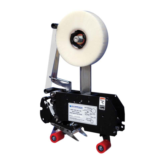
SSISTANCE Technical Support This is the Interpack Model HSD2000-ET II Mirror tape head you ordered. It has been set up and tested in our factory with Intertape manufactured pressure sensitive tapes. If any problems occur when setting up or operating this equipment, please contact the authorized distributor from where you purchased this item. -
Page 5: Warranty
Intertape sells its Interpack Tape Heads, Case Tapers and Case Erectors with the following warranties: ... -
Page 6: Description Of Tape Head
The HSD 2000-ET II Mirror is designed to upgrade most competitive case sealers. Interpack can provide a variety of adapter kits to install this tape head into most case sealers. -
Page 7: Safety Issues
AFETY SSUES There is a safety label used on all Interpack Tape Heads. This label is placed on the Tape Head knife guard to warn operators and service personnel of the sharp cutting edge of the blade. Please read the label and the following safety precautions before using the Tape Head. - Page 8 AFETY SSUES The illustrated label shown in Figure 5-1 is attached to the Knife Guard. The label warns operators and service personnel of the very sharp blade. The guard shall only be removed when the torsion spring or the guard itself is being replaced. Should the tape head be operated without blade guard, user voids all warranty implied, the manufacturer bears no...
- Page 9 AFETY SSUES The illustrated label shown in Figure 5-4 is TAPE ROLL attached to the operator side plate of each PEEL OFF ROLLER tape head. The label provides operators ADHESIVE SIDE and service personnel the proper method of threading a new roll of tape through the tape GUIDE CLUTCH ROLLER...
-
Page 10: Specifications
PECIFICATIONS T ape Head Dimensions U U U Figure 6-1 UH179TW / UH679TW UDH179-02... -
Page 11: T Ape Head Components
PECIFICATIONS T ape Head Components U U U Figure 6-2 UH179TW / UH679TW UDH179-02... -
Page 12: T Ape Head Specifications
PECIFICATIONS O perating Conditions U U U Use in a dry, relatively clean environment at 40º to 105º F (5º to 40º C) with clean, dry cartons. Note: The HSD 2000-ET II Mirror Tape Head should n ever be washed down or subjected U U U U U U to conditions causing condensation on components. -
Page 13: I Nstallation In Other Machinery
Verify the case sizes which will be processed through the case sealer. Installing Interpack HSD 2000-ET II tape heads to process very short cases may cause the tape heads to collide with each other. -
Page 14: S Et Up Procedures
ROCEDURES R eceiving and Handling U U U All contents must be verified upon reception. The following items are included with each tape head. UH 179TW UH 679TW ESCRIPTION 2” W 3” W LATED LATED Main Tape Head assembly SHCS M6 x 8 (part no. UF0810) SS SHCS M6 x 8 (parts no. -
Page 15: M Ounting Adapters
HSD 2000-ET II Tape Heads require Mounting Adapter Hardware to install in any case sealer or case erector. If your Tape Heads are pre-installed in your Interpack or TUFflex case sealer or case erector, you do not need to follow any instructions from this section. If your tape heads will be installed in any other competitive machinery, please review these general guidelines plus any additional instructions included with your HSD 2000-ET II tape head. -
Page 16: T Ape Loading
ROCEDURES T ape Loading U U U The HSD 2000-ET II Mirror Tape Heads accommodate 2-inch (48mm) wide tape rolls, while the HSD 2000-ET II Mirror/3" Tape Heads accommodate 3-inch (72mm) wide rolls. 1. Place the tape head onto a sturdy, flat surface. 2. -
Page 17: T Ape Threading
ROCEDURES ARNING HE KNIFE CONTAINED IN THE EAD IS EXTREMELY SHARP SE CAUTION WHEN REMOVING THE BLADE GUARD AND THREADING THE TAPE TO AVOID PERSONNEL INJURY Tape Threading Preparation Figure 7-5 Threading the tape in the Tape Head does not require any special tools. 1. - Page 18 ROCEDURES TAPE ROLL PEEL OFF ROLLER ADHESIVE SIDE GUIDE CLUTCH Adhesive Side ROLLER ROLLER GUIDE ROLLER TAPE GUIDE SHOE APPLICATION ROLLER Guide Roller Clutch Roller Figure 7-6 Figure 7-7 1. As illustrated in Figures 7-6 & 7-7, first thread the tape tail over the Peel Off Roller.
-
Page 19: T Ape Centering
ROCEDURES T ape Centering U U U If the tape is not centered as it travels through the tape shoe guide, the tape mandrel can be adjusted in or out to correct this Loosen the M18 inverse jam nut on the rear of the mandrel as shown in Figure 7-8 with a 10 mm allen key. -
Page 20: T Ape Leg Length Adjustment
ROCEDURES T ape Leg Length Adjustment U U U For optimum performance, the tape leg length has been factory set at 2 inches (50 mm). However, the tape leg length can be modified. Front Tape Leg To adjust the tape leg length on the leading end of the box, refer to Figure 7-12 of the clutch assembly. -
Page 21: One Way Clutched Roller Adjustment
ROCEDURES One Way Clutched Roller Adjustment This one direction, tensionable roller assures that proper tension is present when cutting the tape. It is preset at the factory but should re-adjustment be necessary, follow these steps: 1. Decrease all mandrel tension. 2. -
Page 22: M Andrel Tension Adjustment
ROCEDURES M andrel Tension Adjustment U U U Mandrel tension is required to control over spin of a full tape roll after the case is finished processing. The tension is set at the factory and no change to the tension should be necessary since the peel off roller should control the over spin in most cases. -
Page 23: Troubleshooting
However, should a problem occur, we recommend that you consult the following table. If the problem you encounter is not discussed in this table, call Interpack Technical Support. (See page 4 of this document). ROUBLE... - Page 24 ROUBLESHOOTING ONTINUED ROUBLE OSSIBLE AUSES OLUTIONS “Tape Tabbing” or folding Generally, too much tension on itself on the trailing tape on the application of the tape. Follow steps below Applying urethane rollers, Remove any adhesive build up delrin guide rollers, knurled with silicon spray.
- Page 25 ROUBLESHOOTING ONTINUED ROUBLE OSSIBLE AUSES OLUTIONS Front tape leg too long Tape threaded incorrectly Check for proper tape threading against threading diagram on side plate of tape head Tape leg length misadjusted Re-set front tape leg length Rear tape leg too short Generally, too much tension Follow corrective action in “Tape on the application of the tape...
-
Page 26: R Ecommended Spare Parts List
ECOMMENDED PARE ARTS We recommend that you stock the following spare parts. These parts are contained in the “spare parts kit” indicated below. The components of the spare parts kits are also referenced should individual components need to be ordered. HSD 2000-ET II 2”... - Page 27 ECOMMENDED PARE ARTS HSD 2000-ET II 3” Wide Spare Parts Kit UH 1003 Parts Contained in UH 1003 Spare Parts Kit ODEL UMBER ESCRIPTION UMBER UANTITY SS Cut-Off Blade 75mm NC UPH0271 SS Ext. Spring UPH0910 Roller shell ETM 3’’ UPH0966 SS Main Spring ETM.080 UPH1091...
-
Page 28: Preventive Maintenance
REVENTIVE AINTENANCE ARNING URN OFF ELECTRICAL POWER SUPPLY AND DISCONNECT THE POWER CORD FROM THE ELECTRICAL SUPPLY BEFORE BEGINNING TO WORK ON THE EADS OR TO LOAD TAPE POWER CORDS ARE NOT DISCONNECTED SEVERE INJURY TO PERSONNEL COULD RESULT The HSD 2000-ET II Mirror has been designed and manufactured with the finest components to provide long, trouble free performance. -
Page 29: O Iler Pad Lubrication
REVENTIVE AINTENANCE L ubrication U U U The HSD 2000-ET II Mirror tape heads ship from the factory permanently lubricated. No additional lubrication is necessary, however, a small amount of lightweight oil applied to rotating and pivot points will extend the life of the tape head and assure maximum performance. There is, however a felt pad on the blade guard which can serve as an oiler pad to help clean the blade should adhesive accumulate. -
Page 30: U Rethane Wipe Down Roller Replacement
REVENTIVE AINTENANCE U rethane Wipe Down Roller Replacement U U U These red rollers are wear items and should be inspected regularly and replaced if necessary. Front & Rear Wipe Down Roller Replacement Removing The Urethane Roller 1. Using a snap ring pliers, remove the snap ring from the roller shaft. -
Page 31: S Pring Replacements
REVENTIVE AINTENANCE S pring Replacements U U U There are 3 springs on the HSD 2000-ET II. These springs are wear items and should be inspected regularly and replaced if necessary. Below are instructions for replacing the two most common springs. Main Spring Replacement 1. - Page 32 REVENTIVE AINTENANCE Knife Arm Spring Replacement If the compression spring breaks, the sequence to change it is as follows. 1. Carefully open the snap ring with a plier and slide it up on the cross shaft. Remove the snap ring attached to the knife arm assembly.
- Page 33 REVENTIVE AINTENANCE 3. Remove the spring barrel from over lapping position as shown in Figure 10-9. Remove any broken particle from the spring guide. Install new compression spring into the captive position. Figure 10-9 4. Press the spring barrel against the spring mandrel until it is ready to slide back on the short shaft.
- Page 34 REVENTIVE AINTENANCE Knife Guard Spring Replacement As a precaution, remove the cutter blade to avoid injury Figure 10-12 Remove the cross shaft NOTE: These screws are secured with loctite and may require applied heat prior to removal 1. Using two 2mm hexagonal keys as shown, remove one of the flathead countersink screws by applying force on both hexagonal key in an attempt to...
- Page 35 REVENTIVE AINTENANCE Carefully slide out the shaft from the end of the shaft that contains the remaining flathead countersink screw Figure 10-14 Remove the broken spring Figure 10-15 UH179TW / UH679TW UDH179-02...
- Page 36 REVENTIVE AINTENANCE Behind The Cutter Blade To properly orient the new knife spring Position the new knife spring as shown in Figure 10-16. Note which leg of the spring should lie behind the cutter blade mounting plate Note which leg of the spring should wrap around the front of the knife guard In Front Of...
- Page 37 REVENTIVE AINTENANCE To Complete The Installation Apply some Blue Loctite to the threads of the M3 screw and fasten to the end of the cross shaft. Tighten using two 2mm hexagonal keys as shown in Figure 10-18 Rotate the knife guard to make sure there is no binding Re-install the cutter blade as shown in Figure 10-12...
-
Page 38: W Ipe Down Brush Replacement
REVENTIVE AINTENANCE W ipe Down Brush Replacement U U U This multi row brush assists in wiping down the top center seam of the case. While the red wipe down rollers perform much of the wipe down, the wipe down brush enhances the wipe down as it can better conform to the irregularities of the top of the case such as over fills, void fills and the “wash-board”... -
Page 39: S Chedule Of Preventive Maintenance
CHEDULE REVENTIVE AINTENANCE Frequency Item Action Required Material Weekly Monthly Quarterly Lubricate Lightweight oil Blade Guard Oiler Pad Hardware Re-tighten any loose hardware Replace any missing hardware Cutter Blade Inspect for wear Clean Solvent Cleaner Disassemble & Observe Mandrel Assembly Mandrel Spring Check for weakness None Mandrel Friction Washer Clean... -
Page 40: A Ppendix A-Illustrations And Parts Lists
A –I & P PPENDIX LLUSTRATIONS ARTS ISTS Tape Head Sub-Assembly ……………………………………………………………………………………. 42 Main Frame Sub-Assembly……………………………………………………………………………………. 44 Front Cover Frame Sub-Assembly……………………………………………………………………………. 46 Rear Cover Frame Sub-Assembly…………………………………………………………………....48 Rear Arm Assembly……………………………………………………………………………………………. 50 Clutch Assembly..…………………………………………………………………………………....52 Mandrel Assembly…………………...…………………………………………………………………………… 54 Peel-Off Arm Assembly………………………………………………………………………………... ……….. 56 Link Assembly………………………………………………………………………………………….... - Page 41 THIS PAGE INTENTIONALLY BLANK...
- Page 43 ITEM PART # DESCRIPTION UH179T/QTY. UH679T/QTY. USH1066 MAIN FRAME 2" MIRROR USH1067 MAIN FRAME 3" MIRROR USH1068 FRONT COVER FRAME MIRROR USH1069 REAR COVER FRAME MIRROR USH1070 REAR COVER FRAME MIRROR USH0931 REAR ARM ASS'Y 48 MIR USH0932 REAR ARM ASS'Y 72 MIR USH1071 CLUTCH ASS'Y 48 MIRROR USH1072...
-
Page 44: Main Frame Sub-Assembly
MAIN FRAME... - Page 45 USH1066 - 2" USH1067 - 3" ITEM PART # DESCRIPTION /QTY. /QTY. UPH3755 MAIN ASS'Y FRAME MIRROR UPH3638 SPACER BAR UPH9041 SPACER BAR UPH3665 SPACER BAR UPH7259 SPACER BAR UPH3636 ARMS PIVOT SHAFT ETM II UPH3664 ARMS PIVOT SHAFT ETM II UPH0872 STOP RETAINER ETM UPH133...
-
Page 46: Front Cover Frame Sub-Assembly
FRONT COVER FRAME... - Page 47 USH1068 ITEM PART # DESCRIPTION QTY. UPH9108 FRONT COVER FRAME MIRROR UF5404 FHCS M5 - 0.8 x 16 mm UF5400 FHCS M5-0.8 x 12 mm UPH133 STOP, URETHANE KNIFE ARM UPH0872 STOP RETAINER ETM...
-
Page 48: Rear Cover Frame Sub-Assembly
REAR COVER FRAME... - Page 49 USH1069 - 2" USH1070 - 3" ITEM PART # DESCRIPTION QTY. QTY. UPH9104 REAR COVER FRAME MIRROR UF5404 FHCS M5 - 0.8 x 16 mm UPH3655 BRUSH 2" UPH3674 BRUSH 3" UPH3640 RETAINER, MAIN SPRING 2" UPH3666 RETAINER, MAIN SPRING 3" UF6303 EXT.
-
Page 50: Rear Arm Assembly
REAR ARM... -
Page 52: Clutch Assembly
CLUTCH ASSEMBLY... - Page 53 USH1071 USH1072 ITEM NO. PART NUMBER DESCRIPTION /QTY. /QTY. UPH3715 CLUTCH BRACKET ET II MIR UPH0887 GUIDE ROLLER SHAFT UPH0949 GUIDE ROLLER SHAFT UPH0888 GUIDE ROLLER ETM UPH0950 GUIDE ROLLER ETM UPH1028 CLUTCH SHAFT UPH1254 CLUTCH SHAFT UAH0220 CLUTCH W. BEARINGS 48 MIRROR UAH0221 CLUTCH W.
-
Page 54: Mandrel Assembly
MANDREL ASSEMBLY... -
Page 56: Peel-Off Arm Assembly
PEEL OFF ARM ASSEMBLY... -
Page 58: Link Assembly
LINK ASSEMBLY... -
Page 60: Front Arm Assembly
FRONT ARM... - Page 61 ITEM PART # DESCRIPTION USH1064/QTY. USH1065/QTY. UAH0013 MIR TAPE SHOE 48 UAH0014 MIRROR TAPE SHOE 72 UAH0074 GUIDE ROLLER W. BEARINGS 48 UAH0075 GUIDE ROLLER W. BEARINGS 72 UF6301 RETAINING RING FOR 10 mm SHAFT UPH0775 ROLLER SHELL UPH0966 ROLLER SHELL UF6389 NYLON F.W.
-
Page 62: Tape Shoe Assembly
TAPE SHOE ASSEMBLY 2 10 3 11... - Page 63 UAH0013 - 2" UAH0014 - 3" UAH0015 - 2" SS UAH0016 - 3" SS ITEM PART # DESCRIPTION QTY. QTY. QTY. QTY. UPH3712 MIRROR TAPE SHOE ET II 48 UPH3722 MIRROR TAPE SHOE ET II 72 UPH0882 TAPE SHOE GUIDE L.H. UPH1021 SS TAPE SHOE GUIDE L.H.
-
Page 64: Knife Arm Assembly
KNIFE ARM... -
Page 66: Repulsive Pivot Assembly
REPULSIVE PIVOT ASSEMBLY...
Need help?
Do you have a question about the HSD2000-ET II MIRROR and is the answer not in the manual?
Questions and answers