Table of Contents
Advertisement
Quick Links
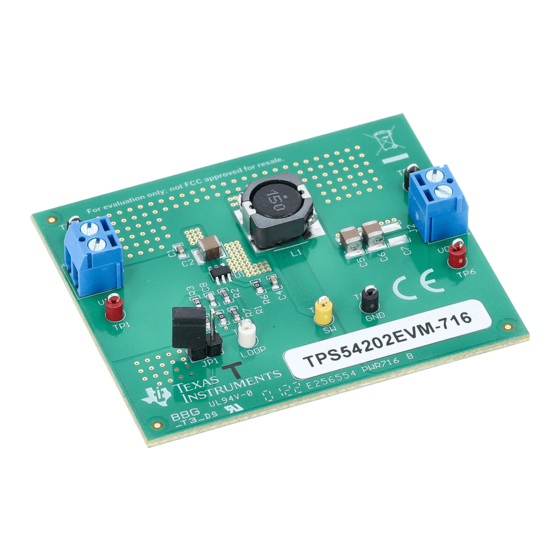
TPS54202EVM-716 2-A Regulator Evaluation Module
...................................................................................................................
1
2
3
4
Schematic and Bill of Materials
1
2
3
4
5
6
7
TPS54202EVM-716 Output Ripple, I
8
9
TPS54202EVM-716 Output Ripple, I
10
11
12
TPS54202EVM-716 Startup Relative to Enable
13
14
TPS54202EVM-716 Shutdown Relative to EN
15
16
17
1
2
3
4
5
SLVUAP3 - April 2016
Submit Documentation Feedback
.....................................................................................................
................................................................................................................
...........................................................................................
.............................................................................................
.....................................................................................
......................................................................................
= 2 A
OUT
= 100 mA
OUT
= 10 mA
OUT
= 0 A
OUT
........................................................................................
................................................................................
...............................................................................
..........................................................................................
.......................................................................................
.........................................................................................
.....................................................................................
Copyright © 2016, Texas Instruments Incorporated
Contents
List of Figures
.............................................................................
...............................................................................
..........................................................................
.....................................................................
.......................................................................
...........................................................................
............................................................................
IN
.......................................................................
.........................................................................
IN
.........................................................................
List of Tables
.............................................................................
.............................................................
TPS54202EVM-716 2-A Regulator Evaluation Module
User's Guide
SLVUAP3 - April 2016
2
4
13
15
5
5
6
6
7
8
8
9
9
10
11
11
12
12
13
14
15
2
2
3
4
16
1
Advertisement
Table of Contents

Related Manuals for Texas Instruments TPS54202EVM-716


Summary of Contents for Texas Instruments TPS54202EVM-716
-
Page 1: Table Of Contents
TPS54202EVM-716 2-A Regulator Evaluation Module This user's guide contains background information for the TPS54202 as well as support documentation for the TPS54202EVM-716 evaluation module (PWR716-001). Also included are the performance specifications, the schematic, and the bill of materials for the TPS54202EVM-716. Contents ........................ -
Page 2: This User's Guide Contains Background Information For The Tps54202 As Well As Support Documentation For The Tps54202Evm-716 Evaluation Module (Pwr716-001). Also Included Are The Performance
This user's guide contains background information for the TPS54202 as well as support documentation for the TPS54202EVM-716 evaluation module (PWR716-001). Also included are the performance specifications, the schematic, and the bill of materials for the TPS54202EVM-716. Background The TPS54202 dc/dc converter is designed to provide up to a 2-A output from an input voltage source of 8 V to 28 V. -
Page 3: Recommended Component Values
ESR, and C8 calculated from Equation 3 should be reduced with medium ESR. Use Table 3 as a starting point. SLVUAP3 – April 2016 TPS54202EVM-716 2-A Regulator Evaluation Module Submit Documentation Feedback Copyright © 2016, Texas Instruments Incorporated... -
Page 4: Test Setup And Results
ENRISING Test Setup and Results This section describes how to properly connect, set up, and use the TPS54202EVM-716 evaluation module. The section also includes test results typical for the evaluation module and covers efficiency, output voltage regulation, load transients, loop response, output ripple, input ripple, and start-up. -
Page 5: Tps54202Evm-716 Efficiency
Output Current (A) D001 Figure 1. TPS54202EVM-716 Efficiency Figure 2 shows the efficiency for the TPS54202EVM-716 on a semi-log scale to better show light load efficiency. The ambient temperature is 25°C. = 24 V, V = 5 V = 12 V, V = 5 V 0.001... -
Page 6: Tps54202Evm-716 Load Regulation
Test Setup and Results www.ti.com Output Voltage Load Regulation Figure 3 shows the load regulation for the TPS54202EVM-716. -0.1 -0.2 -0.3 -0.4 = 24 V = 12 V -0.5 Output Current (A) D003 Figure 3. TPS54202EVM-716 Load Regulation Measurements are given for an ambient temperature of 25°C. -
Page 7: Tps54202Evm-716 Transient Response
Load Transients Figure 5 shows the TPS54202EVM-716 response to load transients. The current step is from 25% to 75% of maximum rated load at 24-V input. Total peak-to-peak voltage variation is as shown, including ripple and noise on the output. -
Page 8: Tps54202Evm-716 Output Ripple, I
Figure Figure 8, and Figure 9 show the TPS54202EVM-716 output voltage ripple for full-load, skip-mode, light-load and no-load operation. V = 24 V. The output The ripple voltage is measured directly across the output capacitors. Figure 6. TPS54202EVM-716 Output Ripple, I = 2 A Figure 7. -
Page 9: Tps54202Evm-716 Output Ripple, I
Test Setup and Results www.ti.com Figure 8. TPS54202EVM-716 Output Ripple, I = 10 mA Figure 9. TPS54202EVM-716 Output Ripple, I = 0 A SLVUAP3 – April 2016 TPS54202EVM-716 2-A Regulator Evaluation Module Submit Documentation Feedback Copyright © 2016, Texas Instruments Incorporated... -
Page 10: Tps54202Evm-716 Input Ripple
Input Voltage Ripple Figure 10 shows the TPS54202EVM-716 input voltage ripple. The output current is the rated full load of 2 A and V = 24 V. The ripple voltage is measured directly across the input capacitors. Figure 10. TPS54202EVM-716 Input Ripple TPS54202EVM-716 2-A Regulator Evaluation Module SLVUAP3 –... -
Page 11: Tps54202Evm-716 Startup Relative To
Powering Up Figure 11 Figure 12 show the start-up waveforms for the TPS54202EVM-716. In Figure 11, the output voltage ramps up as soon as the input voltage reaches the UVLO threshold as set by the R4 and R5 resistor divider network. In... -
Page 12: Tps54202Evm-716 Shutdown Relative To
Powering Down Figure 13 Figure 14 show the start-up waveforms for the TPS54202EVM-716. In Figure 13, the output voltage ramps down as soon as the input voltage falls below the UVLO stop threshold as set by the R4 and R5 resistor divider network. In Figure 14, the output is inhibited by using a 3.3-V logic signal between... -
Page 13: Board Layout
Board Layout www.ti.com Board Layout This section provides a description of the TPS54202EVM-716, board layout, and layer illustrations. Layout Figure 15 Figure 16 show the board layout for the TPS54202EVM-716. The topside layer of the EVM is laid out in a manner typical of a user application. The top and bottom layers are 2-oz. copper. -
Page 14: Tps54202Evm-716 Bottom-Side Layout
Board Layout www.ti.com Figure 16. TPS54202EVM-716 Bottom-Side Layout TPS54202EVM-716 2-A Regulator Evaluation Module SLVUAP3 – April 2016 Submit Documentation Feedback Copyright © 2016, Texas Instruments Incorporated... -
Page 15: Tps54202Evm-716 Schematic
Schematic and Bill of Materials www.ti.com Schematic and Bill of Materials This section presents the TPS54202EVM-716 schematic and bill of materials. Schematic Figure 17 is the schematic for the TPS54202EVM-716. Spacer VIN =8V - 28V VOUT = 5V, 2A Max VOUT 15µH... -
Page 16: Tps54202Evm-716 Bill Of Materials
Schematic and Bill of Materials www.ti.com Bill of Materials Table 5 presents the bill of materials for the TPS54202EVM-716. Table 5. TPS54202EVM-716 Bill of Materials Designator Value Description Package Reference Part Number Manufacturer C1, C4 0.1uF CAP, CERM, 0.1uF, 25V, +/-10%, X5R, 0603... - Page 17 STANDARD TERMS AND CONDITIONS FOR EVALUATION MODULES Delivery: TI delivers TI evaluation boards, kits, or modules, including any accompanying demonstration software, components, or documentation (collectively, an “EVM” or “EVMs”) to the User (“User”) in accordance with the terms and conditions set forth herein. Acceptance of the EVM is expressly subject to the following terms and conditions.
- Page 18 FCC Interference Statement for Class B EVM devices NOTE: This equipment has been tested and found to comply with the limits for a Class B digital device, pursuant to part 15 of the FCC Rules. These limits are designed to provide reasonable protection against harmful interference in a residential installation.
- Page 19 【無線電波を送信する製品の開発キットをお使いになる際の注意事項】 開発キットの中には技術基準適合証明を受けて いないものがあります。 技術適合証明を受けていないもののご使用に際しては、電波法遵守のため、以下のいずれかの 措置を取っていただく必要がありますのでご注意ください。 1. 電波法施行規則第6条第1項第1号に基づく平成18年3月28日総務省告示第173号で定められた電波暗室等の試験設備でご使用 いただく。 2. 実験局の免許を取得後ご使用いただく。 3. 技術基準適合証明を取得後ご使用いただく。 なお、本製品は、上記の「ご使用にあたっての注意」を譲渡先、移転先に通知しない限り、譲渡、移転できないものとします。 上記を遵守頂けない場合は、電波法の罰則が適用される可能性があることをご留意ください。 日本テキサス・イ ンスツルメンツ株式会社 東京都新宿区西新宿6丁目24番1号 西新宿三井ビル 3.3.3 Notice for EVMs for Power Line Communication: Please see http://www.tij.co.jp/lsds/ti_ja/general/eStore/notice_02.page 電力線搬送波通信についての開発キットをお使いになる際の注意事項については、次のところをご覧くださ い。http://www.tij.co.jp/lsds/ti_ja/general/eStore/notice_02.page SPACER EVM Use Restrictions and Warnings: 4.1 EVMS ARE NOT FOR USE IN FUNCTIONAL SAFETY AND/OR SAFETY CRITICAL EVALUATIONS, INCLUDING BUT NOT LIMITED TO EVALUATIONS OF LIFE SUPPORT APPLICATIONS.
- Page 20 Notwithstanding the foregoing, any judgment may be enforced in any United States or foreign court, and TI may seek injunctive relief in any United States or foreign court. Mailing Address: Texas Instruments, Post Office Box 655303, Dallas, Texas 75265 Copyright © 2015, Texas Instruments Incorporated...
- Page 21 IMPORTANT NOTICE Texas Instruments Incorporated and its subsidiaries (TI) reserve the right to make corrections, enhancements, improvements and other changes to its semiconductor products and services per JESD46, latest issue, and to discontinue any product or service per JESD48, latest issue.
Need help?
Do you have a question about the TPS54202EVM-716 and is the answer not in the manual?
Questions and answers