Advertisement
Quick Links
Document Version
Application information
Vehicle
Model
Year of manufacture
Note:
● Read through all instructions before installation and use.
● Ensure that the bike is switched off and the key is out of the ignition before proceeding with the
installation.
● Some parts of the bikes might be hot/sharp and may cause burns/cuts. Proceed with extreme caution
or wait until the bike has cooled down. Always wear safety gloves.
● When the installation is complete, make sure to secure the wiring loom away from the movable parts
or components which tends to heat up during the normal operation of the vehicle at any chance.
● FuelX is intended for motorsport use on a closed course, please check with your local laws before
using this product. Race Dynamics is not liable for consequences arising out of using the product.
Support:
Call: +1 267 214 9292 / +91 9606 044 178
WhatsApp: +91 9606 044 178
E-Mail:
support@powertronicecu.com
Website:
www.powertronicECU.com
FuelX Autotune- Bajaj Dominar
1
FuelX
Bajaj
Dominar
2016-2021
Release Date
14 Sep 2021
1
Advertisement

Related Manuals for Race Dynamics Dominar


Summary of Contents for Race Dynamics Dominar
- Page 1 ● FuelX is intended for motorsport use on a closed course, please check with your local laws before using this product. Race Dynamics is not liable for consequences arising out of using the product. Support:...
- Page 2 SL No Chapter Page About FuelX and Kit Contents Fuel Variants FuelX Connectors FuelX Installation FuelX Configuration...
- Page 3 1. FuelX FuelX is an electronic, plug-in, fuel-injection optimizer for modern engines. It either enriches or decreases the AFR in all operating regions according to the rider requirement. It autotune the engine to best operational parameters, constantly monitoring, learning, and adapting to the engine condition, wear and tear, riding style, add-ons (such as air filter and/or exhaust), etc as well as the environmental conditions such as temperature, humidity, altitude, etc.
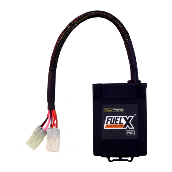
- Page 4 2. FuelX Variants: FuelX Pro The FuelX Pro variant has 10 maps that can be changed depending upon the preference of the rider. For the Pro version, the Fuelx contains an additional connector (Refer Image 2.3) for the Handlebar Map switch(Refer Image 2.2) Image 2.1 Image 2.2 Image 2.3...
- Page 5 3. FuelX Harness Connectors The harness contains only the Lambda connector (O Image 3.1 The type and number of connectors may vary depending on the vehicle, year of manufacture, and the number of cylinders. Examples of different types of Lambda sensor connectors are shown below.
- Page 6 The FuelX is connected between the Lambda sensor connector and the ECU. The male connector of FuelX, connected to the female of the Lambda sensor and vice versa. Image 3.3...
-
Page 7: Installation Procedure
4. Installation procedure Begin at the left side of the bike. Park the bike using the centre stand on a level surface (Or a paddock stand). Refer Image 1 Image 1 Note the position of the Lambda sensor connector. connector/hoses/wires to be removed. Refer Image 2 Image 2... - Page 8 4.1.1 Detach the pillion seat by inserting the key into the keyhole shown in Image 3 and unlock the pillion seat. Image 4 shows how the pillion seat is detached. Image 3 Image 4...
- Page 9 4.1.2 Unscrew the rider seat bolts using M10 Hexagonal Socket - Refer Image 5. Image 5 3.1.3 Refer Image 6 Image 6...
- Page 10 4.1.4 Once the rider seat bolts are removed, gently lift the seat. Refer Image 7. Refer Image 8 for detached view. Image 7 Image 8...
- Page 11 4.1.5 Locate and unscrew the bolts and screws (8 on sides and 2 in the front) using M5 Hexagonal bit and Phillips-head screwdriver. [The tank cover is attached by M5 screw and the panel is attached by screws.] Refer Image 9 for side view and Image 10 for front view.
- Page 12 4.1.6 Once the bolts and screws are removed, gently disconnect the side panel. Refer Image 11. Image 11 4.1.7 Unscrew the cover bolt using M10 Hexagonal T socket. Refer Image 12 and Image 13. Image 12...
- Page 13 Image 13 4.1.8 Remove the cover. Refer Image 14. Image 14...
- Page 14 4.1.9 Gently lift the tank cover and locate the tank cover connector on the left side of the bike. Refer Image 15. Image 15 4.1.10 Disconnect the connector. Refer Image 16. Image 16...
- Page 15 4.1.11 After removing the tank cover connector gently lift the tank cover and place it securely. Refer Image 17 Image 17 4.1.12 Locate the tank bolt in the front end and unscrew it with M14 Hexagonal socket. Refer Image 18 and Image 19 Image 18...
- Page 16 Image 19 4.1.13 Locate the tank side bolt on both sides of the bike. Unscrew it with M12 Ring . Refer Image 20 and Image 21 Image 20...
- Page 17 Image 21 4.1.14 Gently lift the tank. Refer Image 22 Image 22...
- Page 18 4.1.15 Locate and identify the connections under the tank. Note that while removing the fuel line, remove the connector which goes to the throttle body. Refer Image 23 Image 23 4.1.16 Use a nose plier to loosen the metal clamp. Refer Image 24 Image 24...
- Page 19 4.1.17 Refer Image 25 for detached view of tank. Image 25 4.1.18 Locate and unscrew the Phillips head screws of the air filter box. [Two screws are at the rear side of the air-filter box (Refer Image 26) and two screws are in front of the air-filter chamber(Refer Image 27)] Image 26...
- Page 20 Image 27 4.1.19 Route the FuelX harness to the rear end of the vehicle. Refer Image 28 Image 28...
- Page 21 4.1.20 Locate the Lambda Sensor connector on the vehicle. Refer Image 29 Image 29 4.1.21 Gently pull the connector out of the rubber cover. Refer Image 30 Image 30...
- Page 22 4.1.22 Carefully pull the red lock and disconnect the connectors. Refer Image 31 Image 31 4.1.23 Connect the lambda stock male connector to FuelX female connector. Refer Image 32 Image 32...
- Page 23 4.1.24 Connect the lambda stock female connector to FuelX male connector. Refer Image 33 Image 33 4.1.25 Attach the handlebar map switch on the handlebar. Refer Image 34 Image 34...
- Page 24 4.1.26 Using a 2.5 mm Allen key, tighten the screws. Refer Image 35 Image 35 4.1.27 Route the map switch to the rear end of the vehicle. Refer Image 36 Image 36...
- Page 25 4.1.28 Route the map switch to the rear end of the vehicle. Refer Image 37 Image 37 4.1.29 Place the FuelX module on the vehicle. Refer Image 38 Image 38...
- Page 26 4.1.30 Connect the FuelX female 6 pin connector to the harness female 6 pin connector. Refer Image 39 Image 39 4.1.31 Connect the FuelX female 4 pin connector to the handlebar map switch female 4 pin connector. Refer Image 40 Image 40...
- Page 27 4.1.32 Tag the wires securely using the nylon tags provided within the kit. Refer Image 41 Image 41 4.1.33 Attach the panels back after the installation.
- Page 28 5. FuelX Configuration The Red LED on the FuelX blinks once the FuelX activates. For Pro versions, maps on the FuelX can be changed according to the preference of the customer. By just pressing the +/- button on the Handlebar map switch. The green LED on the FuelX Handlebar map switch will help the customer to know which map is currently active.
Need help?
Do you have a question about the Dominar and is the answer not in the manual?
Questions and answers