Table of Contents
Advertisement
Quick Links
PowerTRONIC Installation Manual- KTM Duke 390 (2012-2016)
Document Version
Application information
Vehicle
Model
Year of manufacture
PowerTRONIC application
Note:
● Read through all instructions before installation and use.
● Ensure that the bike is switched off and the key is out of the ignition before proceeding with the
installation.
● Some parts of the bikes might be hot/sharp and may cause burns/cuts. Proceed with extreme
caution or wait until the bike has cooled down. Always wear safety gloves.
● When the installation is complete, make sure to secure the wiring loom away from the movable parts
or components which tends to heat up during the normal operation of the vehicle at any chance.
● PowerTRONIC is intended for motorsport use on a closed course, please check with your local laws
before using this product. Race Dynamics / PowerTRONIC is not liable for consequences arising out
of using the product.
Call/Whatsapp:
E-Mail:
Official Website:
Social:
1
Vehicle Specific
KTM
Duke 390
2012-2016
All PowerTRONIC ECUs, from firmware version F.3.x onward
+919916229292 / +918040929292
support@powertronicECU.com
www.powertronicECU.com
www.facebook.com/PowertronicECU/
www.instagram.com/powertronic_ecu/
Release Date
02 March 2020
1
Advertisement
Table of Contents

Subscribe to Our Youtube Channel
Related Manuals for Race Dynamics PowerTRONIC


Summary of Contents for Race Dynamics PowerTRONIC
- Page 1 ● PowerTRONIC is intended for motorsport use on a closed course, please check with your local laws before using this product. Race Dynamics / PowerTRONIC is not liable for consequences arising out ...
-
Page 2: Table Of Contents
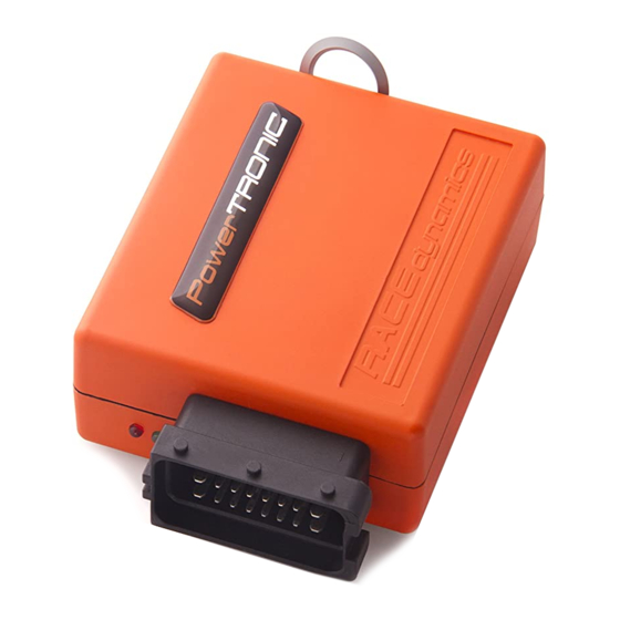
1 PowerTRONIC Piggyback ECU 2 Stock Coupler Stand by unit Can be connected in place of the PowerTRONIC to run the bike in stock ● mode if need be. ● Used for the verification of the connectors involved. 3 ... -
Page 3: Installation Procedure
3. Installation procedure 3.1 Removing panels, fairing Begin at the left side of the bike. Park the bike using the centre stand on a level surface (Or a paddock stand). Refer I mage 1 Image 1 Note the position of the connector/hoses/wires to be removed. Refer I mage 2 ... - Page 4 3.1.1 Detach the pillion seat by inserting the key into the keyhole shown in I mage 3 a nd unlock the pillion seat. I mage 4 shows the pillion seat detached. Image 3 Image 4 ...
- Page 5 3.1.2 L ocate and unscrew the rider seat bolts using M 10 Hexagonal T handle. Refer I mage 5 . Image 5 3.1.3 I mage 6 shows both the seat detached. Image 6 ...
- Page 6 3.1.4 Locate and unscrew the side panel screws 1, 2 and 3 using Phillips head screwdriver and side bolt 4 using M10 hexagonal socket . Refer I mage 7 . Image 7 3.1.4 Locate and unscrew the tank rear screws using a Phillips head screwdriver. Refer I mage 8 . ...
- Page 7 3.1.5 Carefully detach the side panel locks. Refer to I mage 9. Image 9 3.1.5 Carefully unscrew the tank front bolts using 5 mm Allen T handle. Refer to I mage 10. Image 10 ...
- Page 8 3.1.6 U nscrew the tank lid bolts using 4 mm Allen T handle. Refer I mage 11 . Image 11 3.1.7 Carefully detach the tank lid. Refer I mage 12 Image 12 ...
- Page 9 3.1.8 Carefully detach the coolant tank cap. refer I mage 13 . Image 13 3.1.9 Carefully detach the fuel tank cover. Refer I mage 14 . Image 14 ...
-
Page 10: Routing The Harness
3.2 Routing the harness 3.2.1 Place the harness on the bike. Note that the TPS and Ignition coil connectors go to the right side of the bike. All other connectors go to the left. Refer I mage 15 . ... - Page 11 3.2.3 Route the INJ and CKP connectors to the left side of the bike. Refer I mage 17 Image 17 3.2.4 R oute the Ground terminal connector to the battery negative. Refer I mage 18 Image 18 ...
-
Page 12: Fuel Injector Connector
Image 19 3.3.2 I dentify the fuel injector connector in the PowerTRONIC wiring harness. The connectors are labeled 'INJ' 3.3.3 Disconnect the injector connector on your bike. Refer the zoomed view ( I mage 20 ) below. ... - Page 13 3.3.4 Connect the female PowerTRONIC injector connector to the stock male injector connector. Refer I mage 21 Image 21 3.3.5 Connect the stock female injector connector to the PowerTRONIC male injector connector. Refer I mage 22 ...
- Page 14 3.4 Crank position sensor (Left side of the bike) 3.4.1 Locate the stock crankshaft position sensor connector on the bike. Usually located right above the engine. Refer Image 23 . To identify the CKP connector, locate the connector which includes red-white striped wire. ...
- Page 15 3.4.3 Connect PowerTRONIC male CKP connector to the stock female CKP connector. Refer I mage 25 Image 25 3.4.4 Connect the PowerTRONIC female CKP connector to the stock male connector. Refer Image 26 Image 26 ...
-
Page 16: Ignition Coil Connector
3.5.1 Locate the stock Spark/Ignition coil connector on the ignition coil. Refer I mages 27 . Image 27 3.5.2 Identify the Spark/Ignition coil connector in the PowerTRONIC wiring harness. The connectors are labelled 'SPK' 3.5.3 Disconnect the stock ignition coil connectors. Refer I mage 28 below. Image 28 ... - Page 17 3.5.4 Connect the PowerTRONIC Ignition coil male connector to the stock ignition coil female connector. Refer I mage 29 below. Image 29 3.5.5 Connect the PowerTRONIC Ignition coil female connector to the stock ignition coil male connector. Refer I mage 30 ...
- Page 18 3.6 Throttle position sensor connector (Right side of the bike) 3.6.1 Locate the TPS connector of your bike. It is generally located on the throttle body, parallel to the throttle cable return springs. Refer I mage 31 and I mage 32 . ...
- Page 19 3.6.2 Identify the Throttle Position sensor connector in the PowerTRONIC wiring harness, labeled as 'TPS' 3.6.3 Disconnect the stock TPS connector. Refer I mage 33 Image 33 3.6.4 Connect the PowerTRONIC male TPS connector to stock female connector. Refer I mage 34 . Image 34 ...
- Page 20 3.6.5 Connect the PowerTRONIC female TPS connector to stock male connector. Refer I mage 35 . Image 35 3.6.6 We advise you to perform a TPS calibration after the installation of PowerTRONIC ECU. Refer to the detailed TPS calibration document. ...
-
Page 21: Ground Terminal
3 .7 Ground Terminal Connector 3.7.1 Identify the Ground terminal connector labelled GND. Refer I mage 36 Image 36 3.7.2 Connect the ground terminal connector to the negative terminal of the battery. Refer to I mage 37 and I mage 38 . ... - Page 22 Image 38 ...
- Page 23 Image 39 Important note: The PowerTRONIC harness contains a Quick shifter connector. If you have bought the Quickshifter please attach the connector to it. If you have not bought the Quickshifter, you can leave it disconnected but make sure the harness is secured ...
-
Page 24: Testing With Stock Coupler
3.9.1 Attach the fuel tank. 3.9.2 You can verify the connections by attaching the stock coupler. Refer to the detailed Stock coupler test document. 3.9.3 DO NOT proceed with PowerTRONIC ECU without verifying the connections with stock coupler. Refer Image 40 ... -
Page 25: Plugging In The Powertronic
3.10 Plugging in the PowerTRONIC ECU. Connect the PowerTRONIC to the harness by connecting the 24 pin connector. Secure it in the glove box. Refer I mage 41 . Image 41 3.11 Attaching the panels/fairing etc ...
Need help?
Do you have a question about the PowerTRONIC and is the answer not in the manual?
Questions and answers